Bidirectional electromagnetic valve

A two-way solenoid valve and valve cavity technology, used in the field of solenoid valves, can solve the problems of deformation of the main valve body of the solenoid valve, inability to work, and the shell of the solenoid valve is easy to corrode and rust, and achieve the effect of increasing the speed.

Inactive Publication Date: 2020-12-22
秦宇
View PDF0 Cites 1 Cited by
  • Summary
  • Abstract
  • Description
  • Claims
  • Application Information

AI Technical Summary

Problems solved by technology

[0003] However, there are certain defects in the existing two-way solenoid valves: 1. The media used to control the flow of the existing two-way solenoid valves are mostly liquid fluids such as water and oil, and the moving iron core components of the solenoid valves are mostly placed inside the valve cavity for control. The flow direction of the fluid, which will hinder the flow of the viscous fluid in the valve cavity, resulting in unsmooth flow and affecting the rate of fluid flow; The movement will be subject to greater resistance from the fluid, and the electromagnetic force generated by the electromagnetic coil is small, which will easily cause the slider to be stuck in the valve cavity, or make the valve cavity move slowly and affect the working efficiency of the solenoid valve; 3. Solenoid valve Driven entirely by electricity, the solenoid valve will not be able to work in the event of a power outage or other circuit failure; 4. In the assembly line production and processing of the factory, the conveying pipeline needs to work without stopping, and the solenoid valve is replaced repeatedly. When the slider moves in the valve cavity, the fluid will exert a pressure on the inner wall of the valve cavity. Long-term operation will easily deform the main valve body of the solenoid valve or even rupture the cavity wall, thereby affecting the working efficiency of the solenoid valve. In a humid or open-air environment, the casing of the solenoid valve is easily corroded and rusted, reducing the service life of the solenoid valve

Method used


Image

  • Bidirectional electromagnetic valve
  • Bidirectional electromagnetic valve
  • Bidirectional electromagnetic valve

Examples


Embodiment Construction

[0030] The technical solutions of the present invention will be clearly and completely described below in conjunction with the embodiments. Obviously, the described embodiments are part of the embodiments of the present invention, but not all of them. Based on the embodiments of the present invention, all other embodiments obtained by persons of ordinary skill in the art without making creative efforts belong to the protection scope of the present invention.

[0031] In describing the present invention, it should be understood that the terms "center", "longitudinal", "transverse", "length", "width", "thickness", "upper", "lower", "front", " Orientation indicated by rear, left, right, vertical, horizontal, top, bottom, inside, outside, clockwise, counterclockwise, etc. The positional relationship is based on the orientation or positional relationship shown in the drawings, which is only for the convenience of describing the present invention and simplifying the description, rat...


PUM


Abstract

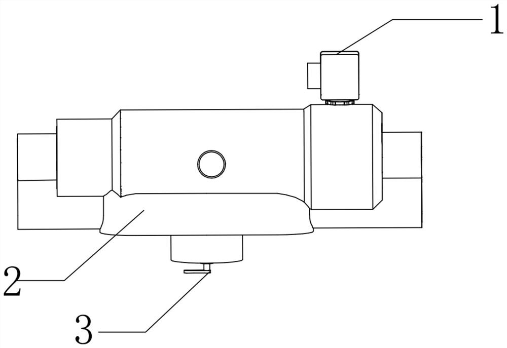
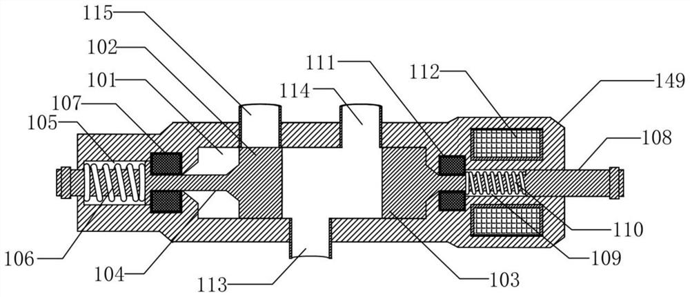
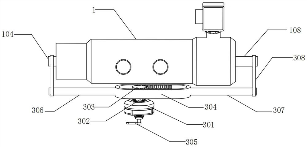
The invention provides a bidirectional electromagnetic valve which comprises a main valve body, a protective shell and a transmission mechanism. The main valve body and the transmission mechanism aresequentially arranged in the protective shell. The main valve body comprises a valve cavity and an outer shell. A first sliding block and a second sliding block are movably installed in the valve cavity. A first movable iron core is fixedly connected to the outer surface of one side of the first sliding block. According to the bidirectional electromagnetic valve, the protective shell is additionally arranged outside the main valve body, deforming or fracturing of the main valve body can be effectively prevented, and the outer shell is prevented from rusting. The transmission mechanism drives the first sliding block and the second sliding block to move, and thus the situation that due to insufficient pushing force of electromagnetic force, the first sliding block and the second sliding block move slowly or get stuck in the valve cavity is avoided. When the electromagnetic valve is powered off or other circuits break down, by rotating a handle, the function of manually controlling reversing of the electromagnetic valve can be achieved, and as no connecting part is between the first sliding block and the second sliding block, the speed of fluid flowing is increased.

Description

technical field [0001] The invention relates to the technical field of solenoid valves, in particular to a two-way solenoid valve. Background technique [0002] Solenoid valve is an industrial equipment controlled by electromagnetic. It is an automatic basic component used to control fluid. It belongs to actuator and is not limited to hydraulic and pneumatic. It is used to adjust the direction, flow, speed and other parameters of the medium in the industrial control system. Solenoid valves can cooperate with different circuits to achieve the desired control, and the control accuracy and flexibility can be guaranteed. There are many kinds of solenoid valves. Different solenoid valves play a role in different positions of the control system. The most commonly used one is the one-way valve. , two-way valve, speed regulating valve, etc. Among them, the two-way solenoid valve is mostly used to control the flow direction of the fluid, and realize the function of one valve body to ...

Claims


Application Information

Patent Timeline
Patent Type & Authority Applications(China)
IPC IPC(8): F16K31/06F16K31/53F16K11/24
CPCF16K11/24F16K31/061F16K31/53
Inventor 秦宇徐连军王俊
Owner 秦宇
Why Eureka
Try Eureka