
Automatic pin inserting machine of IGBT module

A pin-inserting, automatic technology, applied in the manufacture of conveyor objects, electrical components, semiconductor/solid-state devices, etc., can solve the problems of inability to meet the requirements of compact connection, low actual utilization of equipment, and unfavorable automation implementation. The effect of fast pinning operation, compact structure and simple structure

Active Publication Date: 2020-12-22
常州科瑞尔科技有限公司
View PDF5 Cites 5 Cited by
  • Summary
  • Abstract
  • Description
  • Claims
  • Application Information

AI Technical Summary

Problems solved by technology

In the production process of IGBT modules, the IGBT modules are often placed in special trays, which are circulated between various processing procedures in this form. The loading and unloading of the trays needs to be manually placed into the equipment, and the operator needs to be on guard all the time. Next to the equipment, the equipment is idle during the refueling period, the actual utilization rate of the equipment is not high, and the degree of automation is low, which cannot meet the requirements of compact connection between various processes, and is not conducive to the implementation of subsequent automation

Method used


Image

  • Automatic pin inserting machine of IGBT module
  • Automatic pin inserting machine of IGBT module
  • Automatic pin inserting machine of IGBT module

Examples


Embodiment Construction

[0035] Embodiments of the present invention are described in detail below, examples of which are shown in the drawings, wherein the same or similar reference numerals designate the same or similar elements or elements having the same or similar functions throughout. The embodiments described below by referring to the figures are exemplary only for explaining the present invention and should not be construed as limiting the present invention.

[0036] In describing the present invention, it should be understood that the terms "center", "longitudinal", "transverse", "length", "width", "thickness", "upper", "lower", "front", " Back", "Left", "Right", "Vertical", "Horizontal", "Top", "Bottom", "Inner", "Outer", "Clockwise", "Counterclockwise", "Axial" , "radial", "circumferential" and other indicated orientations or positional relationships are based on the orientations or positional relationships shown in the drawings, which are only for the convenience of describing the present ...


PUM


Abstract

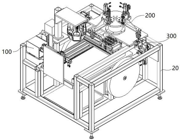
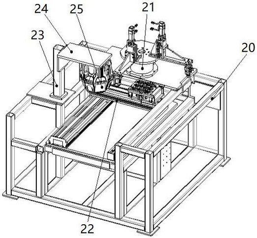
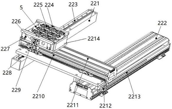
The invention discloses an automatic pin inserting machine of an IGBT module. The machine comprises a rack, an automatic tray feeding device, a pin feeding device and a pin inserting device. The pin inserting device comprises a rotary pin inserting assembly, a tray moving module and a camera detection assembly, and the rotary pin inserting assembly is fixedly arranged on one side, opposite to theautomatic tray feeding device, of the rack; the tray moving module is fixedly arranged on the rack and drives a material tray to move between the automatic tray feeding device and the rotary pin inserting assembly; the camera detection assembly is arranged on the other side, adjacent to the automatic tray feeding device, of the rack and located above the tray moving module. The automatic pin inserting machine is compact in design, high in pin inserting operation speed, suitable for disc-mounted pin feeding, capable of carrying out pin taking and pin inserting actions at the same time and capable of being used for two kinds of pins of different specifications; the camera detection assembly can accurately detect the position of the pin sleeve and the height of the pin, and can detect the position of the pin and the quality after the pin is inserted in real time, thereby achieving the complete automation of the pin insertion operation of the IGBT module.

Description

technical field [0001] The invention belongs to the technical field of automatic pin insertion machines, in particular to an automatic pin insertion machine for IGBT modules. Background technique [0002] IGBT (Insulated Gate Bipolar Transistor), that is, insulated gate bipolar transistor, is the core device of energy conversion and transmission, and is widely used in rail transportation, smart grid, aerospace, electric vehicles and new energy equipment. In order to improve the heat dissipation performance of power devices, increase the service life and reliability, the modular packaging form with smaller volume, higher efficiency and higher reliability has become the main packaging form of high-power IGBT. In the production process of IGBT modules, the IGBT modules are often placed in special trays, which are circulated between various processing procedures in this form. The loading and unloading of the trays needs to be manually placed into the equipment, and the operator ...

Claims


Application Information

Patent Timeline
Patent Type & Authority Applications(China)
IPC IPC(8): H01L21/67H01L21/677
CPCH01L21/67121H01L21/67253H01L21/67742
Inventor 于彬唐光明李昂
Owner 常州科瑞尔科技有限公司
Learn More