
Movable traction hip joint external fixing frame

A fixed frame and hip joint technology, applied in medical science, surgery, etc., can solve the problems of femoral head dislocation, cartilage damage, and high difficulty in surgery

Pending Publication Date: 2020-12-25
SHANGHAI SIXTH PEOPLES HOSPITAL
View PDF0 Cites 2 Cited by
  • Summary
  • Abstract
  • Description
  • Claims
  • Application Information

AI Technical Summary

Problems solved by technology

[0002] In the current orthopedic clinical treatment, if a patient suffers from poor reduction after femoral neck or femoral head fracture, the load-bearing bone trabecula in the femoral head will turn after healing, the load-bearing stress in the load-bearing area will decrease, and stress injury will occur. No discomfort, but secondary necrotic or cartilage damage of the femoral head often occurs after rehabilitative weight-bearing walking
But still can't realize the device and technology of above-mentioned goal at present
[0003] In addition, severe congenital acetabular dysplasia can cause complete dislocation of the femoral head, resulting in severe shortening of the limbs. If subtrochanteric osteotomy and other treatments are not performed during artificial joint replacement, it will be difficult to reset, but the operation is difficult and the damage is large. Complications such as neurovascular injury
It has been reported in the literature that the femoral head can be pulled close to the level of the acetabular preoperatively by lower limb traction, which will greatly reduce the difficulty and risk of surgery and improve the safety of treatment. However, the current traction device requires the patient to stay in bed for a long time, and the controllability is poor. Difficult to nurse, even lead to complications such as hip joint stiffness and decubitus sores, poor feasibility
But still can't realize the device and technology of above-mentioned goal at present

Method used


Image

  • Movable traction hip joint external fixing frame
  • Movable traction hip joint external fixing frame
  • Movable traction hip joint external fixing frame

Examples


Embodiment Construction

[0029] The present invention will be described in detail and concretely below through specific embodiments, so as to make the present invention better understood, but the following embodiments do not limit the scope of the present invention.

[0030] It should be noted that the present invention relates to the field of orthopedic medical devices. Since the bones of the human hip are complex and have certain differences, the attached drawings are only schematic structural diagrams, which need to be adjusted according to the actual bone structure in practical applications, which does not affect the technical solutions of the present invention. spirit and scope.

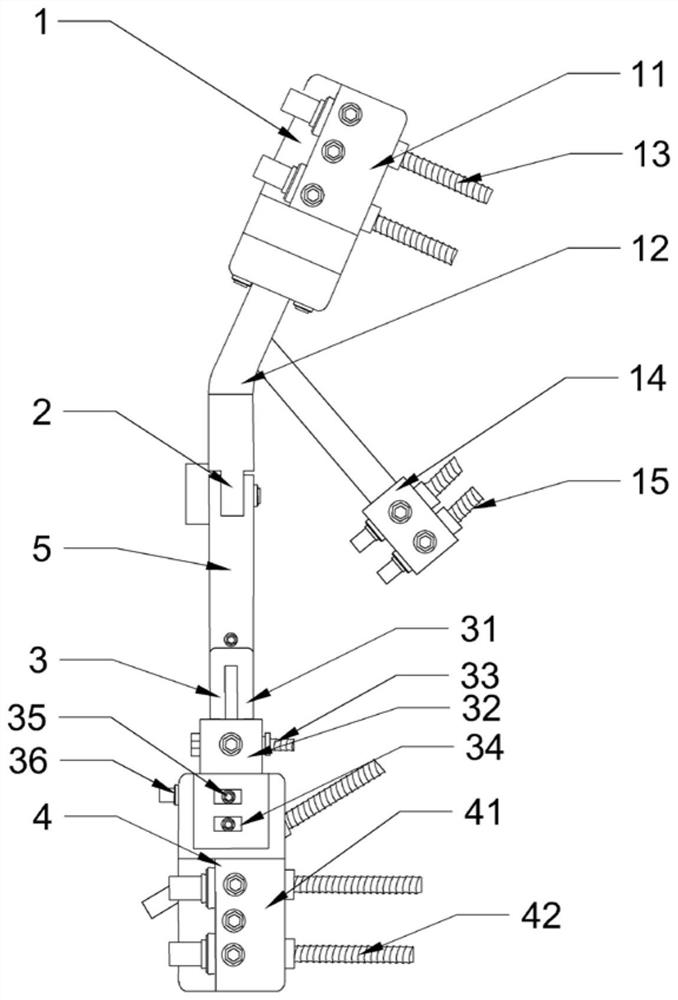
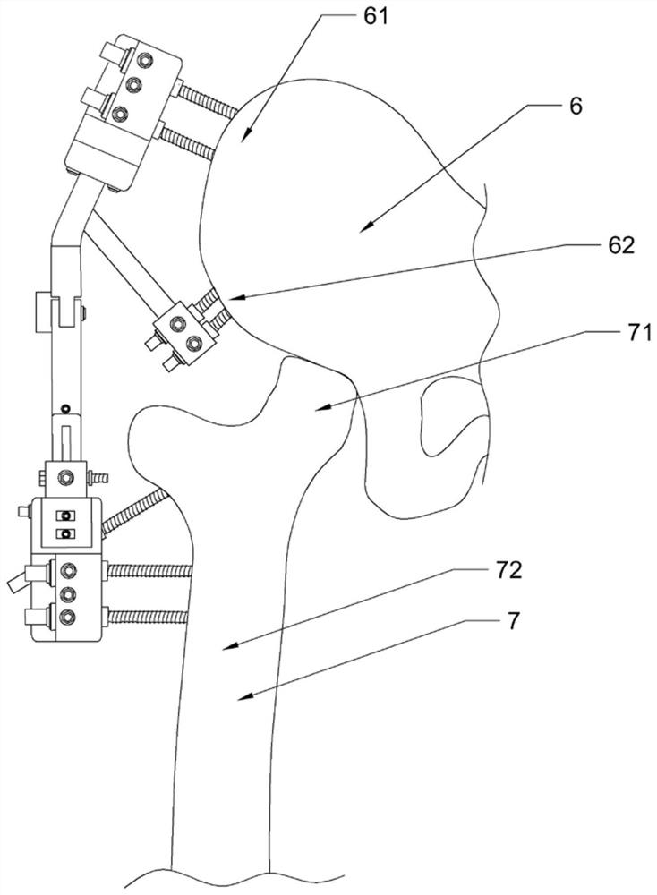
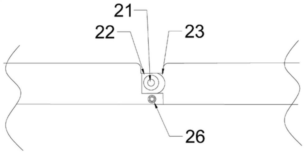
[0031] like figure 1 , the present invention provides a movable traction hip joint external fixation frame, comprising an ilium fixation unit 1, a femoral fixation unit 4 and a middle rod 5, the ilium fixation unit 1 is connected with the middle rod 5 through a hinge movable part 2; The unit 4 is connected with the mid...


PUM


Abstract

The invention discloses a movable traction hip joint external fixing frame. The external fixing frame comprises an ilium fixing unit, a femur fixing unit and a middle rod, wherein the ilium fixing unit is connected with the middle rod through a hinge moving part, the femur fixing unit is connected with the middle rod through a sliding rail moving part, the ilium fixing unit comprises an iliac crest fixing module and an anterior inferior iliac spine fixing module, and the femur fixing unit comprises a femur fixing module. According to the movable traction hip joint external fixing frame, the fixing units are arranged on the ilium and femur respectively, an eccentric distance of the femoral head is recovered and controlled, and the half dislocation tendency of the femur head is resisted; thefemur is dragged, so that the stress of the femoral head is reduced, and the limb shortening is corrected; and the femoral head which is seriously dislocated is dragged to be close to the acetabulumlevel, even the femoral head is reset, and the safety of a hip joint replacement surgery can be improved.

Description

technical field [0001] The invention relates to the field of orthopaedic fixation frame instruments, in particular to a movable traction hip joint external fixation frame. Background technique [0002] In the current orthopaedic clinical treatment, if the patient suffers from poor reduction after the femoral neck or femoral head fracture, the weight-bearing trabecular bone in the femoral head will turn after healing, and the load-bearing stress in the weight-bearing area will be reduced, resulting in stress injury. During the recovery process of the patient No discomfort, but secondary necrosis of the femoral head or cartilage damage often occurs after rehabilitation with weight-bearing walking. Long-term alcoholism or the use of glucocorticoids can also lead to necrosis of the femoral head. On the other hand, femoral head necrosis of the femoral head may occur during the development of children, also known as femoral head necrosis in children. Femoral head necrosis caused...

Claims


Application Information

Patent Timeline
IPC IPC(8): A61B17/60
CPCA61B17/60A61B2017/564
Inventor 杜大江张长青
Owner SHANGHAI SIXTH PEOPLES HOSPITAL
Learn More