Nitrate driving device, system and method thereof

A technology of sleeve barrels and liquid outlets, applied in the direction of feeding devices, chemical instruments and methods, silver compounds, etc., can solve the problems of impurities, equipment wear, waste of steam heat sources, etc., and achieve the effect of improving the speed of nitrate removal

Pending Publication Date: 2020-12-25
昆明先导新材料科技有限责任公司
View PDF0 Cites 0 Cited by
  • Summary
  • Abstract
  • Description
  • Claims
  • Application Information

AI Technical Summary

Problems solved by technology

[0003] The operation of catching up with nitrate in the prior art generally adopts continuous heating and evaporation, constantly adding pure water, and continuously boiling silver nitrate solution to remove redundant nitric acid. Evaporation to remove excess nitric acid in the solution has low nitric acid removal efficiency, which not only causes waste of steam or other heat sources, but also produces a large amount of acidic condensed water containing nitrate radicals, which increases the wastewater treatment cost of the enterprise to a certain extent. Greatly increased production costs
[0004] In the prior art nitrate removal operation, the metal powder is also used to contact the acid-containing solution. After the metal powder and the acid-containing solution fully react, the nitrate removal operation is completed. During the process, a stirring device is often used to stir the metal powder. Although this nitration operation can make the metal powder fully contact with the acid solution and speed up the process of nitration, but directly stirring the metal powder through the stirring device will cause violent movement. , the metal powder particles are easy to rub against the equipment, which will cause equipment wear. What's more, the friction process will cause the solution to introduce new impurities, which will make the subsequent impurity removal more troublesome and bring new impurity problems.

Method used


Image

  • Nitrate driving device, system and method thereof

Examples


Embodiment Construction

[0021] The technical solution will be clearly and completely described below in conjunction with the embodiments of the present invention. Apparently, the described embodiments are only some of the embodiments of the present invention, not all of them. Based on the embodiments of the present invention, all other embodiments obtained by persons of ordinary skill in the art without making creative efforts belong to the protection scope of the present invention.

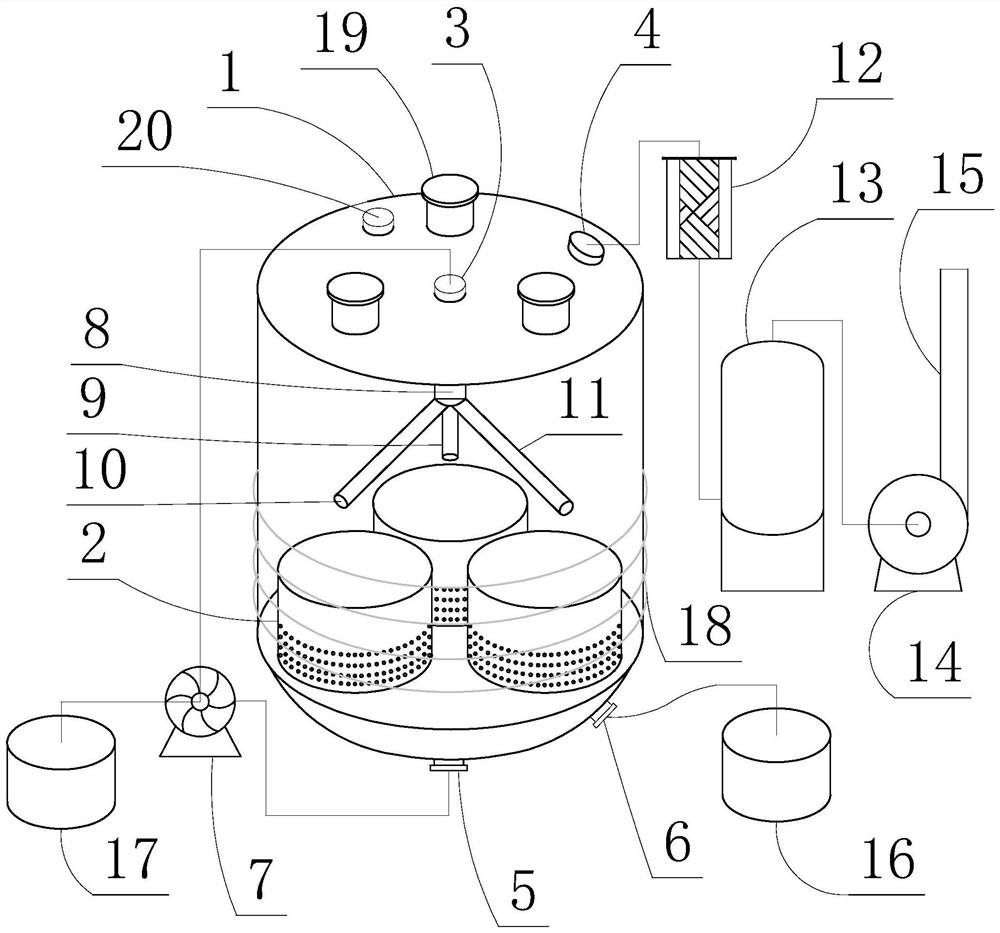
[0022] refer to figure 1 , according to the first aspect of the present invention, a kind of nitration removal device is provided, which includes a nitration removal kettle 1 and an inner sleeve 2 arranged in the nitration removal kettle 1, the lower barrel wall and the bottom of the inner sleeve 2 are evenly distributed Through holes, preferably, through holes are evenly distributed on the lower 1 / 2 barrel wall and bottom of the inner sleeve barrel 2, and there are metal powder particles in the inner sleeve barrel 2, a...


PUM


Abstract

The invention discloses a nitre driving device, which comprises a nitre driving kettle and an inner sleeve barrel arranged in the nitre driving kettle, through holes are evenly distributed in the lower barrel wall and the bottom of the inner sleeve barrel, a first liquid inlet is formed in the top of the nitre driving kettle, a first liquid outlet is formed in the bottom of the nitre driving kettle, the first liquid inlet is communicated with the first liquid outlet through a pipeline, a pump assembly is further arranged between pipelines communicating the first liquid inlet and the first liquid outlet, a first liquid outlet pipe is further arranged in the nitre driving kettle, one end of the first liquid outlet pipe is connected with the first liquid inlet, and the other end of the firstliquid outlet pipe abuts against the upper portion of the inner sleeve barrel. By arranging the pump assembly, a solution is subjected to flowing circulation, the solution makes full contact with metal powder particles, then the nitrate removing speed is increased, the solution circulation plays a role in stirring, and the situation that metal violently moves due to direct stirring of a stirring device is avoided; the technical problems that in the prior art, metal is directly stirred through the stirring device, new impurities are introduced through friction between the metal and equipment, and the nitrate driving speed is low are solved.

Description

technical field [0001] The invention relates to the technical field of equipment for preparing metals and their compounds, in particular to a device, system and method for removing nitrate. Background technique [0002] The purpose of nitrate removal is to remove excess nitric acid in the silver nitrate solution, increase the pH of the solution, and produce high-purity silver nitrate. In the process of using silver powder or silver ingot to prepare silver nitrate crystals, the removal of free nitro groups is a one-step process. A very important production process, especially silver nitrate used as a photosensitive material in the electronics industry. This material has very high requirements on the purity of silver nitrate. The impurity content in silver nitrate directly affects the performance of the material. An important process that cannot be ignored. [0003] The operation of catching up with nitrate in the prior art generally adopts continuous heating and evaporation,...

Claims


Application Information

Patent Timeline
Patent Type & Authority Applications(China)
IPC IPC(8): B01J19/24B01J19/00B01J4/00C01G5/00
CPCB01J4/001B01J4/008B01J19/0006B01J19/0053B01J19/2445B01J19/2465B01J2219/00164B01J2219/1943C01G5/00
Inventor 秦婷婷朱刘邢娜王权石静儒
Owner 昆明先导新材料科技有限责任公司
Why Eureka
Try Eureka