Compact arrangement system for billet discharge area of billet caster

A billet continuous casting, compact technology, applied in the field of the layout of the billet area of ​​the continuous casting machine, can solve the problem of limited space in the workshop, and achieve the effects of wide adjustment range, reduced space area, and compact structure

Active Publication Date: 2020-12-25
马钢集团设计研究院有限责任公司
View PDF12 Cites 5 Cited by
  • Summary
  • Abstract
  • Description
  • Claims
  • Application Information

AI Technical Summary

Problems solved by technology

[0008] Aiming at the current problem that the workshop space in the billet discharge area of ​​the billet continuous casting machine is limited, and the cooling bed, steel transfer machine and other equipment cannot be arranged, the present invention provides a compact layout system for the billet discharge area of ​​the billet continuous caster. The system not only has a compact structure and requires a small workshop area, but also increases the cooling time of the slab on the cooling bed without increasing the length of the cooling bed, which can effectively reduce the occupied space

Method used


Image

  • Compact arrangement system for billet discharge area of billet caster
  • Compact arrangement system for billet discharge area of billet caster
  • Compact arrangement system for billet discharge area of billet caster

Examples


Embodiment 1

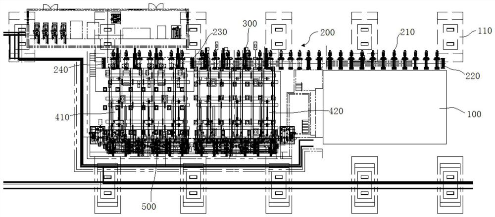
[0048] combine Figure 1-Figure 10 , a compact layout system for the billet discharge area of ​​the billet continuous casting machine in this embodiment, including the lifting baffle 230 arranged on the hot delivery roller table 200 and the two-way cooling bed A 410 arranged on the same side of the hot delivery roller table 200 tail and bi-directional cooling bed B 420, such as figure 1 As shown, in the present embodiment, the two-way cooling bed A 410 and the two-way cooling bed B 420 are all perpendicular to the hot delivery roller table 200, and the two-way cooling bed A 410 is located on the left side of the two-way cooling bed B 420, wherein the two-way cooling bed A 410 and The two-way cooling beds B 420 have the same structure and are arranged parallel to each other. In this embodiment, the side of the hot delivery roller table 200 far away from the two-way cooling bed A 410 and the two-way cooling bed B 420 is provided with an alignment steel pusher 300, and the two a...

Embodiment 2

[0055] A compact layout system for the billet discharge area of ​​the billet continuous casting machine in this embodiment, the basic structure is the same as that of Embodiment 1, further, as Figure 4 As shown, in this embodiment, the lifting baffle 230 includes a baffle housing arranged above, and the left and right sides of the baffle housing are respectively provided with a fixed end surface 238 and a buffer end surface 231, wherein the buffer end surface 231 is detachably inserted into the baffle On the right side of the plate housing, a second fixed screw 232 is connected between the fixed end surface 238 and the buffer end surface 231, and the fixed end surface 238 is provided with a through hole for the second fixed screw 232 to pass through, and one end of the second fixed screw 232 is fixed On the buffer end surface 231 , the other end of the second fixing screw 232 passes through the through hole on the fixing end surface 238 and is limited by a nut. The second fixi...

Embodiment 3

[0059] A compact layout system for the billet discharge area of ​​the billet continuous casting machine in this embodiment, the basic structure is the same as that of Embodiment 2, further, as figure 1 and Figure 9 As shown, in this embodiment, the side of the bidirectional cooling bed A 410 and the bidirectional cooling bed B 420 away from the hot delivery roller table 200 is provided with a collection platform 500, and the collection platform 500 includes a receiving part 510 for receiving the casting slab 110 With the steel dial mechanism 520 for pushing the cast slab 110, the receiving part 510 and the steel dial mechanism 520 are arranged in parallel. Specifically, such as Figure 9 As shown, in the present embodiment, the collection platform 500 is provided with a plurality of receiving parts 510 and a steel dial mechanism 520 evenly spaced along the width direction of the two-way cooling bed A 410 and the two-way cooling bed B 420, which is convenient for the two-way ...


PUM


Abstract

The invention discloses a compact arrangement system for a billet discharge area of a billet caster, and belongs to the technical field of arrangement of billet discharge areas of continuous casting machines. The compact arrangement system comprises a lifting baffle, and a bidirectional cooling bed A and a bidirectional cooling bed B arranged on the same side of the tail of a hot conveying rollerway; the lifting baffle can implement free lifting and is used for performing shunting treatment on casting blanks; the bidirectional cooling bed A and the bidirectional cooling bed B are the same instructure and are arranged in parallel; the operation mode of the bidirectional cooling bed A is alternate operation of forward rotation and reverse rotation; the step number of forward rotation for advancement of the bidirectional cooling bed A is two times of the number of a set of conveyed casting blanks; and the step number of reverse rotation for retreating of the bidirectional cooling bed Ais one time of the number of a set of conveyed casting blanks. Aiming at the problems that the workshop space of a billet discharge area of an existing billet caster is limited and equipment such as cooling beds, a steel moving machine and the like cannot be arranged, the cooling time of the casting blanks on the cooling beds is prolonged when the lengths of the cooling beds are not increased, andthe occupied space area can be effectively reduced.

Description

technical field [0001] The invention belongs to the technical field of arrangement of the billet discharge area of ​​a continuous casting machine, and more specifically relates to a compact arrangement system of the billet discharge area of ​​a billet continuous caster. Background technique [0002] In the billet discharge area of ​​the current billet continuous casting machine, the billet is transported to the lifting baffle through the roller table after the billet leaves the continuous casting machine, and then the fixed-size casting billet is sent to the cooling bed by the steel transfer machine or the steel scooping machine, generally At this time, the billet temperature is about 850°C, so a cooling bed with a considerable length is needed to cool the billet from about 850°C to below 350°C. [0003] In the traditional layout, the direction of the cooling bed in the billet delivery area is perpendicular to the direction of the casting stream, and the entire continuous ca...

Claims


Application Information

Patent Timeline
Patent Type & Authority Applications(China)
IPC IPC(8): B22D11/124B22D11/128
CPCB22D11/1241B22D11/1284
Inventor 徐旭周治宇王勇
Owner 马钢集团设计研究院有限责任公司
Why Eureka
Try Eureka