Full-automatic cut-off machine for stainless steel profile

A fully automatic, stainless steel technology, used in maintenance and safety accessories, metal processing machinery parts, clamping, etc., can solve problems such as adverse health effects of workers, steel cutting offset, steel shaking, etc., to improve safety and The effect of stability, body health protection, quick installation angle

Inactive Publication Date: 2020-12-25
昆山佳欣成精密机械有限公司
View PDF8 Cites 2 Cited by
  • Summary
  • Abstract
  • Description
  • Claims
  • Application Information

AI Technical Summary

Problems solved by technology

[0003] However, there are still some disadvantages in the existing cutting machine. When the equipment is working, it will produce a certain amount of vibration and also produce a certain amount of steel powder, so that the steel placed on the table will shake with the impact of the vibration, resulting in equipment damage to the steel. The cutting is offset, and the inhalation of powder will have an adverse effect on the health of the staff. For this reason, we propose a stainless steel profile automatic cutting machine

Method used


Image

  • Full-automatic cut-off machine for stainless steel profile
  • Full-automatic cut-off machine for stainless steel profile
  • Full-automatic cut-off machine for stainless steel profile

Examples


Embodiment Construction

[0023]In order to make the technical means, creative features, objectives and effects of the present invention easy to understand, the following further describes the present invention in conjunction with specific embodiments, but the following embodiments are only preferred embodiments of the present invention, not all of them. Based on the examples in the implementation manners, other examples obtained by those skilled in the art without creative work shall fall within the protection scope of the present invention. The experimental methods in the following examples are conventional methods unless otherwise specified. The materials and reagents used in the following examples can be obtained from commercial sources unless otherwise specified.

[0024]Example:

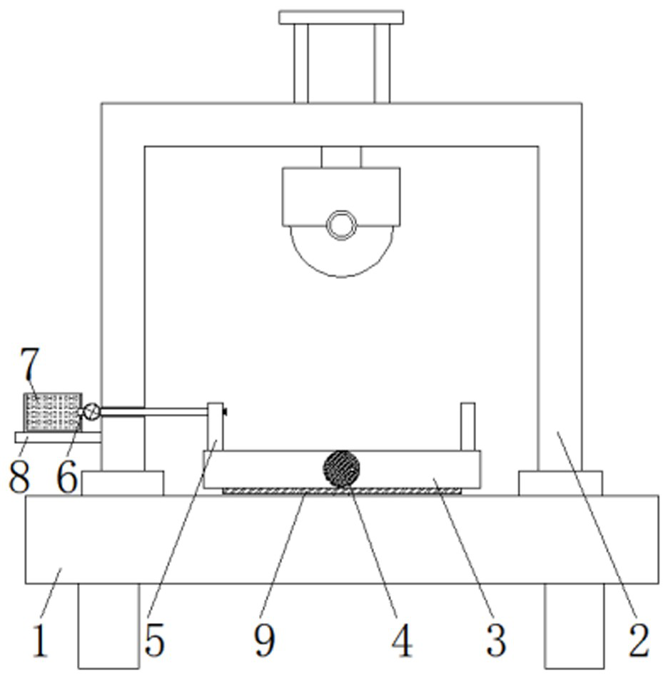
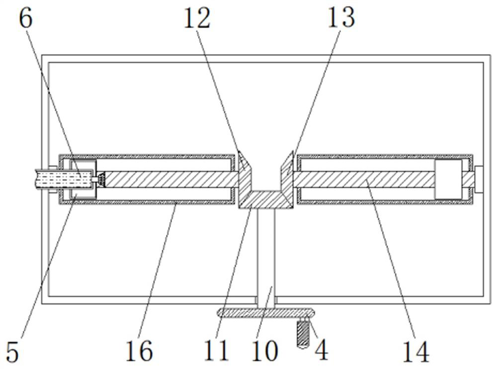
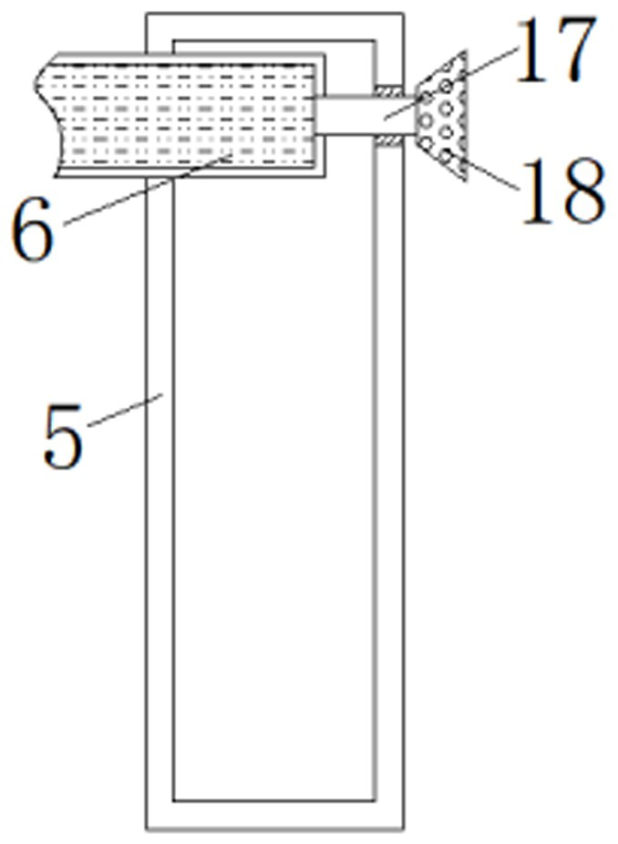
[0025]Such asFigure 1-Figure 3As shown, a stainless steel profile automatic cutting machine includes a base 1, an inverted frame 2 is fixed at the top of the base 1, a placement table 3 is fixed at the top of the base 1, and a bear...


PUM


Abstract

The invention discloses a full-automatic cut-off machine for stainless steel profile. The full-automatic cut-off machine comprises a base, wherein an inverted rack is fixed to the top end of the base;a placing table is fixed to the top end of the base, a first rotating shaft is arranged on the outer wall of the front side of the placing table in a penetrating manner and through a bearing, the first rotating shaft extends to a cavity of the placing table and is rotationally provided with a first bevel gear in a sleeve manner at the tail end, and the two sides of the first bevel gear are in engaged connection to a second bevel gear and a third bevel gear correspondingly; first lead screws rotationally penetrate through the inner walls of the second bevel gear and the third bevel gear, the outer walls of the first lead screws are rotationally sleeved with clamping plates, and sliding grooves allowing the clamping plates to slide are formed in the top end of the placing table; water injection pipes are fixed in cavities of the set of clamping plates, penetrate through the inner wall of one sides of the clamping plates, extends to the outer wall of one side of the rack and are connected to a water tank in an inserted mode at the tail end, and a fixing plate is fixed to the bottom end of the water tank; and connecting pipes are fixed to the surfaces of the sides, located in the cavities of the clamping plates, of the water injection pipes and extend to the outer walls of one sides of the clamping plates, and are fixedly provided with atomizing nozzles at the tail ends of the connecting pipes.

Description

Technical field[0001]The invention relates to the technical field of stainless steel profiles, in particular to a stainless steel profile automatic cutting machine.Background technique[0002]Stainless steel profile is used in engineering construction, based on stainless steel has good corrosion resistance, so it can make structural components permanently maintain the integrity of engineering design. Chromium-containing stainless steel also integrates mechanical strength and high extensibility, and is easy to process and manufacture parts, which can meet the needs of architects and structural designers; a cutting machine is required for its production and processing.[0003]However, the existing cutting machine still has some drawbacks. When the equipment is working, it will produce a certain amount of vibration and also produce a certain amount of steel powder, so that the steel on the placing table will shake with the impact of the vibration, resulting in the equipment’s impact on the...

Claims


Application Information

Patent Timeline
Patent Type & Authority Applications(China)
IPC IPC(8): B23D79/00B23Q3/06B23Q11/00
CPCB23D79/00B23Q3/06B23Q11/0042
Inventor 夏春江
Owner 昆山佳欣成精密机械有限公司
Why Eureka
Try Eureka