
Automatic cutter adjusting device of woodworking lathe follow rest

An automatic adjustment device and technology for woodworking lathes, which are applied in woodworking lathes, wood processing appliances, manufacturing tools, etc., can solve the problems of the quality of processing operations, the impact of the surrounding environment, poor shock absorption and stability, and unfavorable promotion and use. Integrated and flexible performance, extended service life, and the effect of promoting and using

Inactive Publication Date: 2020-12-25
湖州南浔博锐木工刀具有限公司
View PDF0 Cites 0 Cited by
  • Summary
  • Abstract
  • Description
  • Claims
  • Application Information

AI Technical Summary

Problems solved by technology

[0003] At present, most of the woodworking lathes on the market need to adjust the clamping parts of the tool holder according to the workpiece specifications before use. The operation is more complicated, which affects the actual processing efficiency, and the existing tool holders have a relatively low shock absorption and stability effect in actual operations. Poor, a large amount of sawdust will be produced during lathe operation, which will affect the quality of processing work and the surrounding environment. At present, some devices that can clean these sawdust mostly use fan adsorption, but ignore the high-speed rotation of the workpiece. , when the sawdust is separated from the workpiece, the residual potential energy on it can drive it to get rid of the suction effect generated by the negative pressure produced by the fan, and then the sawdust will still be scattered around the lathe. The actual cleaning effect is not ideal, which is not conducive to popularization and use.

Method used


Image

  • Automatic cutter adjusting device of woodworking lathe follow rest
  • Automatic cutter adjusting device of woodworking lathe follow rest
  • Automatic cutter adjusting device of woodworking lathe follow rest

Examples


Embodiment Construction

[0021] The following will clearly and completely describe the technical solutions in the embodiments of the present invention with reference to the accompanying drawings in the embodiments of the present invention. Obviously, the described embodiments are only some, not all, embodiments of the present invention. Based on the embodiments of the present invention, all other embodiments obtained by persons of ordinary skill in the art without making creative efforts belong to the protection scope of the present invention.

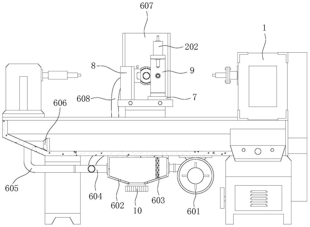
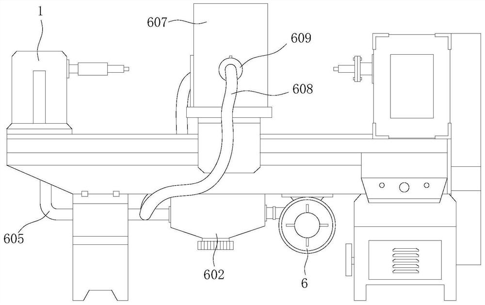
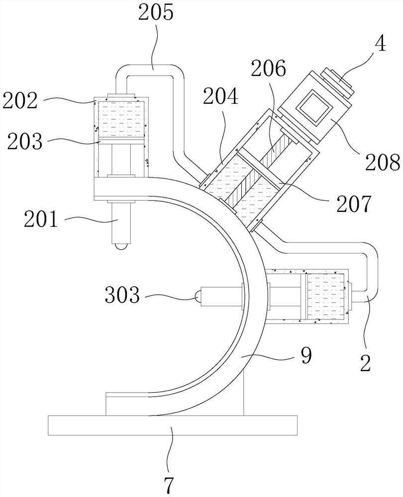
[0022] see Figure 1-5 , the present invention provides a technical solution: a tool automatic adjustment device for a woodworking lathe tool rest, including a lathe body 1, a tool follower mechanism 2, a vibration suppression mechanism 3 and a cleaning mechanism 6 are arranged on the lathe body 1, and the lathe body 1 The top of the saddle is welded with base 7 and two groups of knife rest bodies 8, and the top outer surface of base 7 is welded with U-shaped ...


PUM


Abstract

The invention discloses an automatic cutter adjusting device of a woodworking lathe follow rest, and relates to the technical field of woodworking lathes. The automatic cutter adjusting device of thewoodworking lathe follow rest comprises a lathe body, a follow mechanism, a vibration suppression mechanism and a cleaning mechanism are arranged on the lathe body, a base and two sets of cutter restbodies are welded to the top of a saddle of the lathe body, a U-shaped seat is welded to the outer surface of the top of the base, and the two sets of cutter rest bodies are symmetrically distributed.According to the automatic cutter adjusting device of the woodworking lathe follow rest, the pressure of a contact on a workpiece is automatically adjusted to be stabilized within a proper range, anoperator does not need to carry out fine and complex adjusting operation, the labor burden of the operator is relieved, the output pressure of the contact on the workpiece is stable, the machining quality of the workpiece is guaranteed, and the practicability of the device is improved; and the machining time is shortened, the machining efficiency is improved, and meanwhile, a damping spring further plays a role in suppressing surface vibration of the workpiece during machining operation of the lathe body.

Description

technical field [0001] The invention relates to the technical field of woodworking lathes, in particular to an automatic tool adjustment device for woodworking lathes and tool holders. Background technique [0002] A lathe is a machine tool that mainly uses a turning tool to turn a rotating workpiece. On the lathe, drills, reamers, reamers, taps, dies and knurling tools can also be used for corresponding processing. The lathe mainly includes the spindle box, feed Giving boxes, skateboards, saddles, tool holders, tailstocks and beds, etc. [0003] At present, most of the woodworking lathes on the market need to adjust the clamping parts of the tool holder according to the workpiece specifications before use. The operation is more complicated, which affects the actual processing efficiency, and the existing tool holders have a relatively low shock absorption and stability effect in actual operations. Poor, a large amount of sawdust will be produced during lathe operation, whi...

Claims


Application Information

Patent Timeline
IPC IPC(8): B27C7/00B27G3/00
CPCB27C7/00B27G3/00
Inventor 李兴权
Owner 湖州南浔博锐木工刀具有限公司
Learn More