Hydraulic automatic tablet pressing machine

An automatic tablet press and hydraulic technology, applied in the direction of presses, material forming presses, manufacturing tools, etc., can solve problems such as safety hazards, cumbersome operations, and the inability to never touch the start button by mistake, so as to ensure uniform pressing Effects of force bearing, elimination of operational safety hazards, and convenient operation

Pending Publication Date: 2020-12-25
南安市鄂丰机械有限公司
View PDF0 Cites 0 Cited by
  • Summary
  • Abstract
  • Description
  • Claims
  • Application Information

AI Technical Summary

Problems solved by technology

[0003] Existing hydraulic tablet presses generally include main structures such as a machine base, a frame, an upper die (stroke adjustment) and a hydraulic cylinder. The tableting mold for the distribution is placed between the upper mold and the pressure plate at the telescopic end of the hydraulic cylinder, and the hydraulic cylinder is driven by the telescopic end of the hydraulic cylinder to extend out and cooperate with the fixed upper mold to press the distribution in the tableting mold into a high-density sheet structure. During the use of the existing hydraulic tablet press, it is found that there are several points to be improved: the base of the traditional hydraulic tablet press and the frame are generally exposed on all s

Method used


Image

  • Hydraulic automatic tablet pressing machine
  • Hydraulic automatic tablet pressing machine
  • Hydraulic automatic tablet pressing machine

Examples


Embodiment 1

[0040] Such as Figure 4As shown, the stroke adjustment mechanism 3 includes a nut seat 301 embedded and installed on the top of the frame body 2. The upper end of the nut seat 301 has a square flange structure, and the four corners of the square flange structure are fixed to the top of the frame body 2 by countersunk head screws. The inner cavity of the nut seat 301 is screwed with an adjusting stud 302, the lower end of the adjusting stud 302 is fixedly provided with a limit plate 303, and the upper end of the adjusting stud 302 is equipped with an adjusting knob 304, which is convenient for applying force to rotate the adjusting stud 302 to adjust The height of the limit pressing plate 303, the outer wall of the adjusting stud 302 and the top of the frame body 2 are screwed with a locknut 305, and the locknut 305 can be locked downwards to prevent adjustment when abutting against the top of the frame body 2 The effect of stud 302 loosening.

Embodiment 2

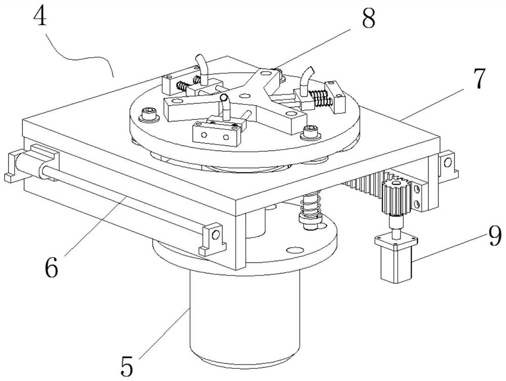
[0042] Such as Figure 5 As shown, the double guide rail mechanism 6 includes two translation sliders 601 arranged at intervals on the left and right sides. The two translation sliders 601 are parallel to each other. 2. On the inner walls of both sides, linear bearing seats 603 are slidably installed on the two translation sliding rods 601 respectively. It can slide axially along the translation slide bar 601 when force is applied.

Embodiment 3

[0044] Such as Figure 6 As shown, the translation mounting seat mechanism 7 includes a horizontal mounting plate 701, the left and right sides of the bottom of the horizontal mounting plate 701 are respectively fixed with mounting side plates 702 for installing the linear bearing seat 603, and the bottom front side of the horizontal mounting plate 701 is installed with The sealing panel 703 plays an aesthetic role ( figure 2 Hidden block panel 703), the middle part of the horizontal mounting plate 701 is provided with a relief opening 704, to facilitate the passage of the top telescopic end of the hydraulic cylinder 5, the circumference of the relief opening 704 is evenly embedded with three bushings 705, and the bushing 705 The inner cavities are all slidably equipped with a lifting slide bar 706, and the upper end of the lifting slide bar 706 is fixedly installed with the mold bearing platform mechanism 8. A limit stop is set and fixed by an axial screw.

[0045] When th...


PUM


Abstract

The invention discloses a hydraulic automatic tablet pressing machine in the technical field of tablet pressing machines. The hydraulic automatic tablet pressing machine comprises a main machine seat,a frame body arranged on the main machine seat, a stroke adjusting mechanism arranged at the top of the frame body, a die driving mechanism assembly arranged in the main machine seat and the frame body, and a safety panel component arranged at the front side of the frame body, wherein the die driving mechanism assembly comprises a hydraulic cylinder installed in the main machine seat, double-guide-rail mechanisms installed on the inner walls of the two sides of the frame machine body, a horizontal movement installation seat mechanism arranged between the double-guide-rail mechanisms and horizontally installed on the double-guide-rail mechanisms in a sliding manner, a die bearing table mechanism arranged on the horizontal movement installation seat mechanism and installed on the horizontalmovement installation seat mechanism in a manner of floating up and down, and a motor driving mechanism arranged in the main machine seat and driving the horizontal movement installation seat mechanism to carry out horizontal movement. The invention provides a hydraulic automatic tablet pressing machine which much facilitates placing and taking for a die, and capable of effectively eliminating the potential safety hazards of operation.

Description

technical field [0001] The invention relates to the technical field of tablet presses, in particular to a hydraulic automatic tablet press. Background technique [0002] A machine that places granular or powdered materials (such as diamond powder) in a tablet die and then presses it into tablets with a punch is called a tablet press. Diamond composite material is a special material widely used. Usually, a certain proportion of diamond particles is added to the matrix material, and the diamond particles are embedded in the matrix as hard points and wear-resistant phases. Its performance mainly depends on the diamond The performance of itself and the performance of the carcass material used to enclose diamond particles, the carcass material can be metal, alloy, resin, ceramics and rubber. It has excellent physical properties such as high hardness, good wear resistance, good thermal stability, etc., and has extremely high chemical stability, so it is widely used in the field o...

Claims


Application Information

Patent Timeline
IPC IPC(8): B30B11/06B30B15/00B30B15/04B30B15/28
CPCB30B11/06B30B15/00B30B15/041B30B15/28
Inventor 张绪元
Owner 南安市鄂丰机械有限公司
Why Eureka
Try Eureka