Underframe of all-aluminum carriage
A technology for carriages and underframes, which is applied to vehicle components, substructures, transportation and packaging, etc., can solve the problems of low welding strength, scattered force, easy failure, etc., and achieves low processing costs, distributed stress and simplified bottom beam Effect
- Summary
- Abstract
- Description
- Claims
- Application Information
AI Technical Summary
Problems solved by technology
Method used
Image
Examples
Embodiment 1
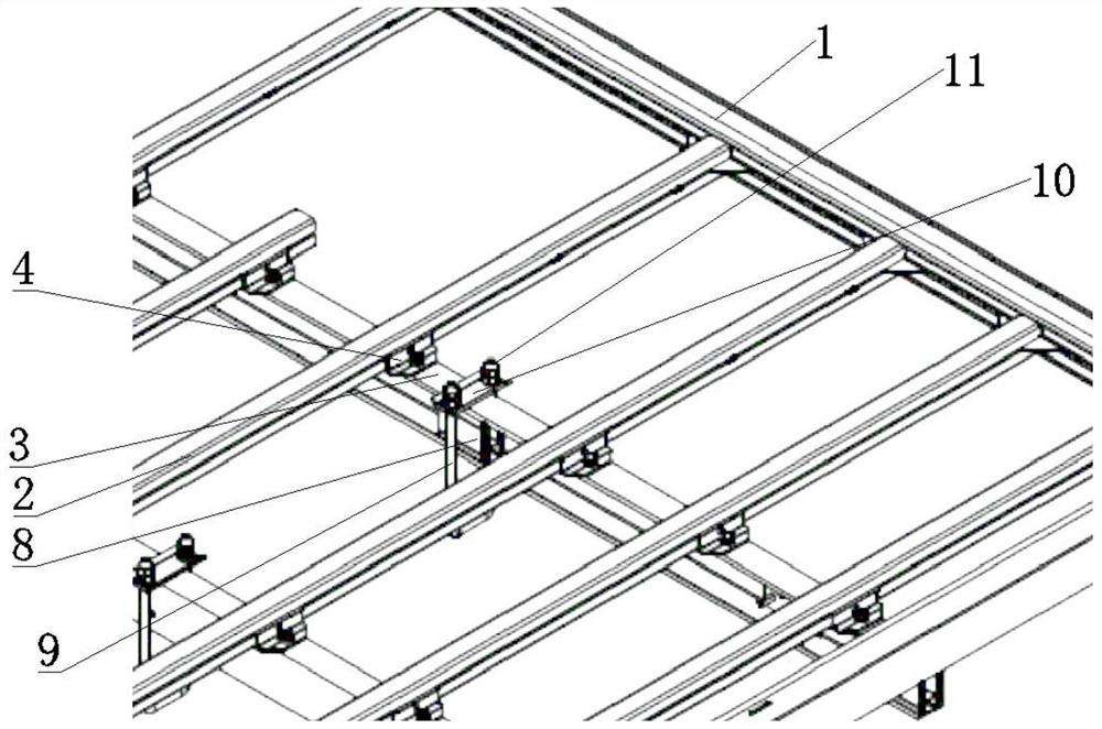
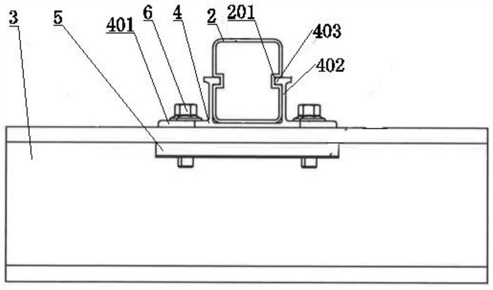
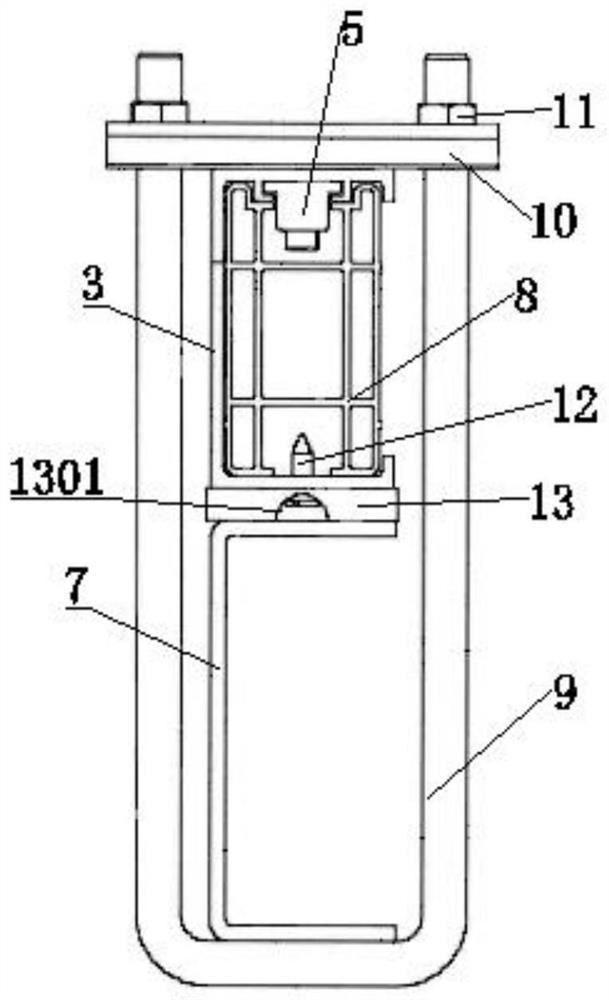
[0037] Such as Figure 1~3 As shown, as shown, an underframe of an all-aluminum carriage includes a bottom frame 1, a bottom beam 2 and an auxiliary longitudinal beam 3, the bottom beam 2 and the auxiliary longitudinal beam 3 are cross-connected, and the auxiliary longitudinal beam 3 It is connected with the frame 7 of the vehicle body, and the secondary longitudinal beam 3 is configured as a channel structure provided with openings in the horizontal direction. Bolt 6, the beam double support 4 includes a base 401 arranged in pairs and a slot 402 arranged above the middle of the base 401, the bottom beam 2 is fixed in the slot 402, and the bolts 6 pass through in turn Through the base 401, the upper side of the auxiliary longitudinal beam 3 and the cover pad 5, the bolt 6 and the sleeve pad 5 are screwed and fastened; the connecting structure of the auxiliary longitudinal beam 3 and the vehicle body frame 7 includes Support block 8, U-shaped bolt 9, pressure plate 10 and nut ...
Embodiment 2
[0041] Such as Figure 1~3 As shown, an underframe of an all-aluminum carriage includes a bottom frame 1, a bottom beam 2 and an auxiliary longitudinal beam 3. The bottom frame 1 includes four bottom frame 1 beams connected in a rectangular shape, and each of the bottom beams 2 Both sides of the auxiliary longitudinal beam 3 are connected with the beams of the bottom frame 1 to form the chassis of the carriage.
[0042] Such as figure 2 As shown, the bottom beam 2 and the auxiliary longitudinal beam 3 are cross-connected, the auxiliary longitudinal beam 3 is connected to the vehicle body frame 7, and the auxiliary longitudinal beam 3 is configured as a channel structure provided with openings in the horizontal direction. The connection structure between the bottom beam 2 and the auxiliary longitudinal beam 3 includes a double beam support 4, a sleeve pad 5 and a bolt 6, and the double beam support 4 includes a base 401 arranged in pairs and a plug set above the middle of the...
Embodiment 3
[0053] The difference between this implementation and the above-mentioned embodiment 2 is that a single support is used to connect the bottom frame of the front and rear of the car and the auxiliary longitudinal beam, and the length of the support block 8 along the longitudinal direction of the auxiliary longitudinal beam 3 is 110mm, and it can mainly It is used to avoid the stress concentration problem at the connection node, and avoids the weight increase caused by the too long support block 8 .
PUM
 Abstract
Description
Claims
Application Information
 - R&D
- Intellectual Property
- Life Sciences
- Materials
- Tech Scout
- Unparalleled Data Quality
- Higher Quality Content
- 60% Fewer Hallucinations
Browse by: Latest US Patents, China's latest patents, Technical Efficacy Thesaurus, Application Domain, Technology Topic, Popular Technical Reports.
© 2025 PatSnap. All rights reserved.Legal|Privacy policy|Modern Slavery Act Transparency Statement|Sitemap|About US| Contact US: help@patsnap.com


