Pressure compensation type hydraulic pump, rotating speed control system, rotating speed control method and engineering machinery

A technology for construction machinery and rotational speed control, which is applied to fluid pressure actuating system components, mechanical equipment, fluid pressure actuating devices, etc., and can solve the problems of loud fan noise, inability to stabilize fan speed, and affecting the cooling effect of hydraulic system. , to achieve the effect of stable work

Pending Publication Date: 2020-12-25
ZOOMLION HEAVY IND CO LTD +1
View PDF0 Cites 7 Cited by
  • Summary
  • Abstract
  • Description
  • Claims
  • Application Information

AI Technical Summary

Problems solved by technology

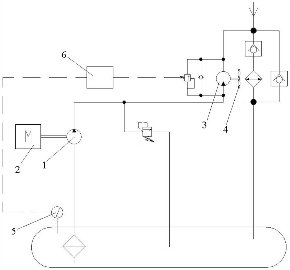
[0004] However, during the working process of construction machinery, the rotational speed of the engine 2 will change with the change of the load, and the change of the rotational speed of the engine 2 will cause the rotational speed of the cooling pump 1 to change, so that the output flow of the cooling pump 1 will also change, and the output flow of the cooling pump 1 will also change. Fluctuations in the output flow will lead to fluctuations in the speed of the fan motor 3, resulting in fluctuations in the speed of the fan 4, and the speed of the fan 4 cannot be stabilized at the required value. This affects the cooling effect of the hydraulic system on the one hand, and on the other hand Makes the fan 4 make a lot of noise

Method used


Image

  • Pressure compensation type hydraulic pump, rotating speed control system, rotating speed control method and engineering machinery
  • Pressure compensation type hydraulic pump, rotating speed control system, rotating speed control method and engineering machinery
  • Pressure compensation type hydraulic pump, rotating speed control system, rotating speed control method and engineering machinery

Examples


Embodiment Construction

[0052]Specific embodiments of the present invention will be described in detail below in conjunction with the accompanying drawings. It should be understood that the specific embodiments described here are only used to illustrate and explain the present invention, and are not intended to limit the present invention.

[0053] In the description of the present invention, it should be noted that unless otherwise specified and limited, the terms "connection" and "arrangement" should be understood in a broad sense, for example, it can be a fixed connection or a detachable connection, or a Integral connection; it can be a direct connection, or an indirect connection through an intermediary, and it can be the internal communication of two elements or the interaction relationship between two elements. Those of ordinary skill in the art can understand the specific meanings of the above terms in the present invention according to specific situations.

[0054] The terms "first", "second...


PUM


Abstract

The invention relates to engineering machinery, and specifically discloses a pressure compensation control type hydraulic pump. The hydraulic pump comprises an electric proportional pressure compensator, a hydraulic pump, a hydraulic control reversing valve and a servo piston, the electric proportional pressure compensator can be electrically connected with a controller, a first hydraulic controlport of the hydraulic control reversing valve is connected with an internal oil drainage oil way through the electric proportional pressure compensator, the first hydraulic control port is connected to an internal output oil way through a hydraulic control oil-inlet oil way provided with a first throttling valve, a second hydraulic control port of the hydraulic control reversing valve is connectedwith the internal output oil way, and the pressure difference between the opening pressure of the electric proportional pressure compensator and the pressure of an oil outlet of the hydraulic pump can drive the hydraulic control reversing valve to reverse. In this way, a rodless cavity of the servo piston selectively communicates with the internal output oil way or the internal oil drainage oil way. In addition, the invention further discloses a rotating speed control method, a rotating speed control system and engineering machinery. According to the hydraulic pump, the output flow of the hydraulic pump can be stabilized at a required value.

Description

technical field [0001] The present invention relates to engineering machinery, in particular to a method for controlling the rotational speed of heat dissipation equipment for engineering machinery. In addition, the present invention also relates to a pressure compensation control hydraulic pump, a speed control system for heat dissipation equipment of construction machinery and construction machinery. Background technique [0002] During the operation of large-scale construction machinery, part of the pressure energy of its hydraulic system will be converted into heat energy, which will increase the oil temperature of the hydraulic system. In order to maintain the temperature of the hydraulic oil within a reasonable range, it is necessary to use heat dissipation equipment to dissipate heat from the hydraulic oil. Large-scale construction machinery such as excavators and loaders generally adopt an independent heat dissipation control system, that is, the input shaft of the ...

Claims


Application Information

Patent Timeline
Patent Type & Authority Applications(China)
IPC IPC(8): F15B21/08F15B21/0423F15B11/042F15B11/05F15B13/02
CPCF15B21/087F15B21/0423F15B11/0426F15B11/05F15B13/021
Inventor 刘象宝田永丰易波吴元峰邓付军
Owner ZOOMLION HEAVY IND CO LTD
Why Eureka
Try Eureka