Backlight module and display device

A backlight module and backlight board technology, applied in optics, nonlinear optics, instruments, etc., can solve problems such as complex processing procedures, poor welding, and increased costs, and achieve low processing and assembly process requirements, reduce processing procedures, and reduce The effect of production costs

Active Publication Date: 2020-12-25
XIAMEN TIANMA MICRO ELECTRONICS
View PDF5 Cites 0 Cited by
  • Summary
  • Abstract
  • Description
  • Claims
  • Application Information

AI Technical Summary

Problems solved by technology

There are the following disadvantages in the process of using the pull welding process: First, the connection between the light source and the main binding area is in a bare state, and it is necessary to add an insulating tape to the connection to avoid contact between the connection and the outside water vapor. Short circuit, corrosion and other problems, the processing procedure is complicated, which increases the cost; second, due to long-term welding, the temperature of the main binding area and the light source will increase, which will cause the problem of light source brightness attenuation or floating height; third, pull welding The process requirements are high, and poor welding is prone to lead to false welding or welding deviation, thereby reducing the overall quality, resulting in rising costs and customer complaints.

Method used


Image

  • Backlight module and display device
  • Backlight module and display device
  • Backlight module and display device

Examples


Embodiment Construction

[0025] Exemplary embodiments of the present disclosure will be described in more detail below with reference to the accompanying drawings. Although exemplary embodiments of the present disclosure are shown in the drawings, it should be understood that the present disclosure may be embodied in various forms and should not be limited by the embodiments set forth herein. Rather, these embodiments are provided for more thorough understanding of the present disclosure and to fully convey the scope of the present disclosure to those skilled in the art.

[0026] It should be understood that the terminology used herein is for the purpose of describing particular example embodiments only and is not intended to be limiting. As used herein, the singular forms "a", "an" and "the" may also be meant to include the plural forms unless the context clearly dictates otherwise. The terms "comprising", "comprising", "containing" and "having" are inclusive and thus indicate the presence of stated...


PUM


Abstract

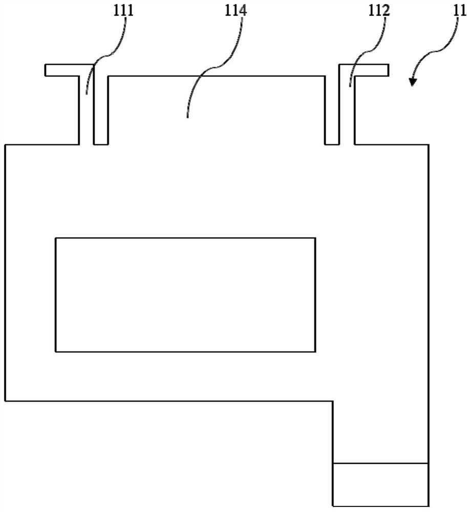
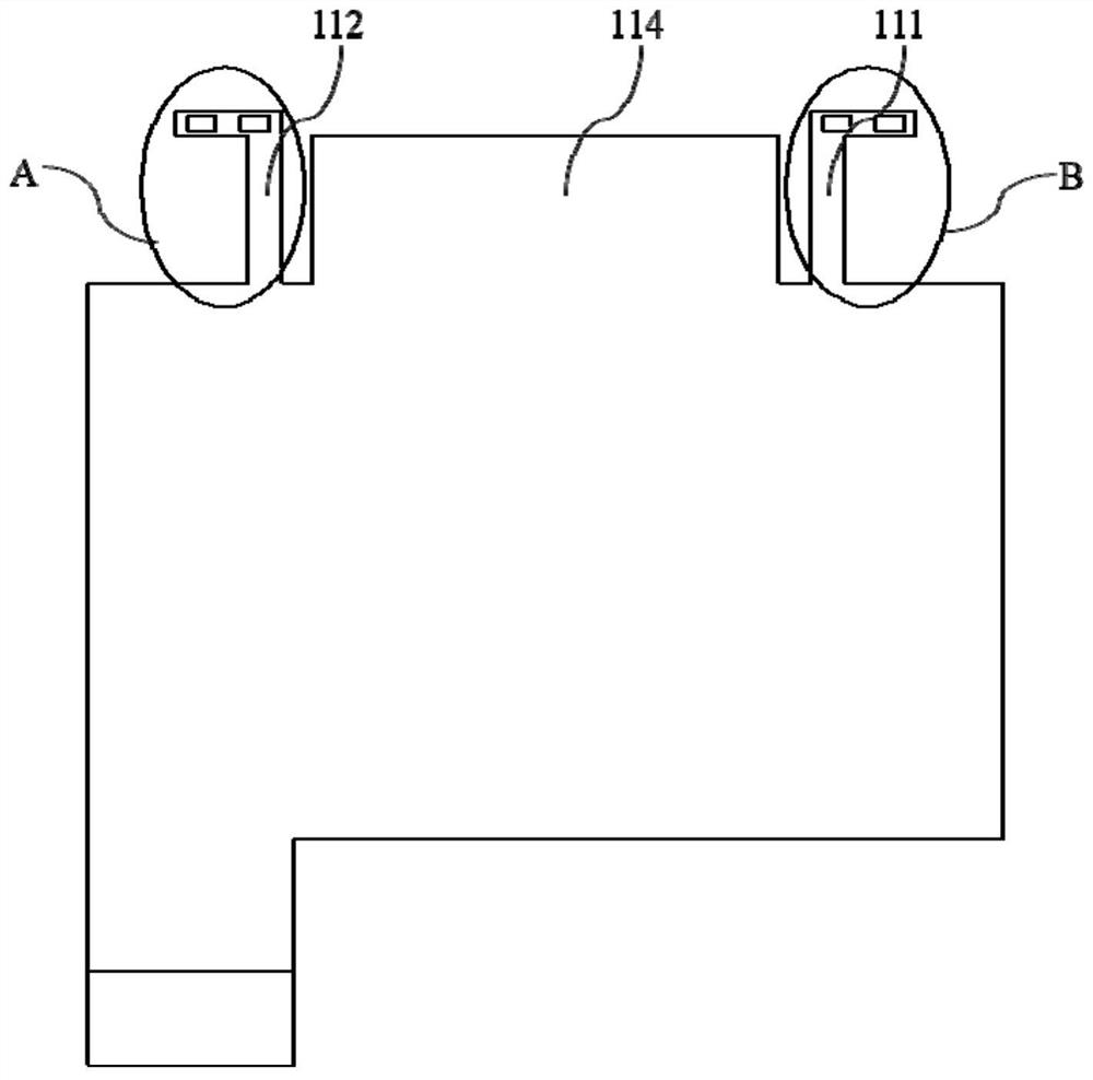
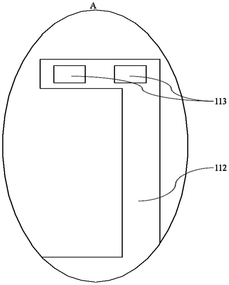
The invention belongs to the field of display, and particularly relates to a backlight module and a display device. The backlight module comprises a flexible circuit board, a backlight board and a conductive part, wherein the flexible circuit board comprises a main binding area and at least two lugs; the lugs are arranged on the main binding area; a first bonding pad is arranged on each lug; the main binding area is connected with an IC port; a light source is arranged on the backlight board; and a second bonding pad is arranged on the light source; and the first bonding pad and the second bonding pad are electrically connected through the conductive part to conduct the light source. According to the backlight module provided by the embodiment of the invention, the design of an extension part on the light source is cancelled, and the lugs arranged on the flexible circuit board replace the extension part, so that an insulating tape is not used any more, the processing procedure of attaching the insulating tape is reduced and the processing efficiency is improved. The lugs are electrically connected with the light source through the conductive part, and a pull welding process is notadopted any more, so that the problem of brightness attenuation or floating height of the light source caused by temperature rise of the main binding area and the light source due to long-term weldingis solved and the overall quality is improved.

Description

technical field [0001] The present application belongs to the display field, and in particular relates to a backlight module and a display device. Background technique [0002] This section provides background information related to the present disclosure only and is not necessarily prior art. [0003] In the manufacturing process of the backlight module, the main binding area and the light source are included, wherein the main binding area is connected with the control circuit of the backlight module, and the light source is connected with the backlight circuit of the backlight unit in the backlight module. [0004] In the prior art, the light source is provided with a protruding part, and solder is used to connect the protruding part and the pad of the main bonding area together, so as to realize the conduction and transmission of electrical signals, but this method needs to fix the light source and the bonding pad first. The location of the main binding area, and then th...

Claims


Application Information

Patent Timeline
Patent Type & Authority Applications(China)
IPC IPC(8): G02F1/13357
CPCG02F1/1336
Inventor 郭单余
Owner XIAMEN TIANMA MICRO ELECTRONICS
Why Eureka
Try Eureka