Shielding ball

A technology of shielding balls and spheres, applied in electrical components, insulators, circuits, etc., can solve the problem of corona-prone shielding balls, and achieve the effect of enhancing the supercharged shielding effect, not easy to corona, and small field strength

Active Publication Date: 2020-12-25
STATE GRID CORP OF CHINA +2
View PDF5 Cites 0 Cited by
  • Summary
  • Abstract
  • Description
  • Claims
  • Application Information

AI Technical Summary

Problems solved by technology

[0005] The purpose of the present invention is to provide a shielding ball to solve the technical problem that the corona phenomenon is prone to occur at the perforation of the shielding ball in the prior art

Method used


Image

  • Shielding ball
  • Shielding ball
  • Shielding ball

Examples


specific Embodiment 1

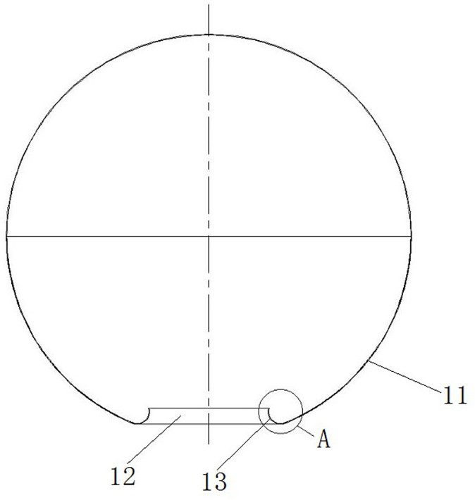
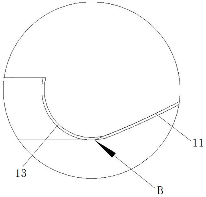
[0033] Such as Figure 3 to Figure 6 As shown, the shielding ball includes a sphere 200, and two perforations 23 ( Figure 4 Only the perforation 23 at the lower end is shown in the figure), arc-shaped flanges 24 are provided at the edges of the two perforations 23 to even out the electric field, and the sphere 200 and the arc-shaped flanges 24 are smoothly connected.

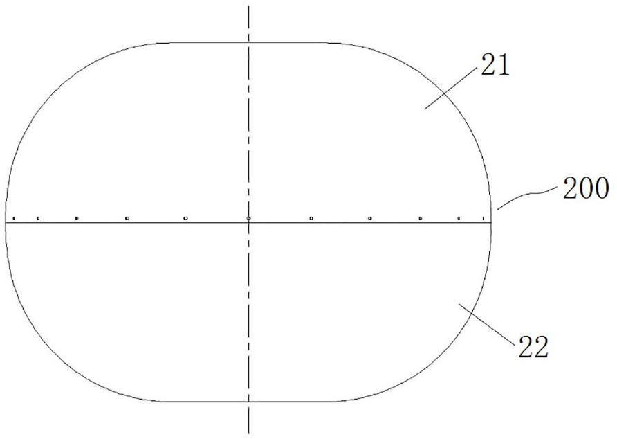
[0034] Such as Figure 4 As shown, the sphere 200 includes an upper hemisphere 21 and a lower hemisphere 22. The upper and lower hemispheres are combined to form a sphere 200. A connecting ring 25 is welded inside the lower hemisphere 22. The connecting ring 25 is welded against the inner wall of the lower hemisphere 22. A plurality of threaded holes are evenly distributed along the circumferential direction on the upper surface. After welding, each threaded hole is located on the horizontal plane where the center of the lower hemisphere is located. Countersunk holes are evenly distributed on the outer periph...

Embodiment 1

[0043] In Embodiment 1, a connecting ring is fixed on the lower hemisphere, and a counterbore is provided on the upper hemisphere. In this embodiment, the connecting ring is fixed on the upper hemisphere, and a counterbore is provided on the lower hemisphere.

specific Embodiment 3

[0045] In Embodiment 1, the upper and lower hemispheres are detachably connected by screws. In this embodiment, after the upper and lower hemispheres are respectively processed, they are fixedly connected together by welding.


PUM


Abstract

The invention relates to a shielding ball which comprises a ball body, the ball body is a revolving body arranged in a revolving mode around a central axis extending up and down, at least one end of the ball body in the vertical direction is provided with a through hole, the central axis of the through hole is collinear with the central axis of the ball body, and the edge of the through hole is provided with an arc-shaped flanging; in the vertical plane where the central axis of the ball body is located, the arc-shaped flanging is provided with a flanging arc section, the ball body comprises amiddle arc section located in the center in the vertical direction, a transition section located at the end of the ball body in the vertical direction and a connecting section connecting the middle arc section with the transition section, and the connecting section is in tangent smooth transition with the middle arc section and the transition section. The curvature radius of the transition section is larger than that of the flanging arc section, the flanging arc section is located on the side, facing the sphere center, of the transition section, and the flanging arc section and the transitionsection are in tangent smooth transition.

Description

technical field [0001] The invention relates to a shielding ball. Background technique [0002] The valve hall of the converter station is a closed space for AC and DC conversion. The corona phenomenon is serious at the end of the busbar, the slot and the corner in the valve hall. The corona phenomenon will cause a series of adverse effects. Add shielding balls at the bottom and corners to improve the anti-corona capability. The shielding ball can shield the fitting itself and the end of the insulator to avoid corona. [0003] Existing shielding balls such as figure 1 and figure 2 As shown, the shielding ball includes a sphere 11 with the same diameter. The lower end of the sphere 11 is provided with an insulator perforation 12 for the insulator to penetrate. The arc-shaped flange 13 that is turned upward, in order to further improve the shielding performance of the shielding ball, has a smooth transition between the arc-shaped flange 13 and the ball 11 . Specifically,...

Claims


Application Information

Patent Timeline
Patent Type & Authority Applications(China)
IPC IPC(8): H01B17/42H01B17/38H02G7/00
CPCH01B17/42H01B17/38H02G7/00
Inventor 王文豪赵重阳张炜付江浩高荣刚王晶赵建平张跃张力方张盼王旭辉牛雨欣
Owner STATE GRID CORP OF CHINA
Why Eureka
Try Eureka