Armature assembly and 1/2 crystal cover magnetic latching relay

A relay and armature technology, which is applied in the field of 1/2 crystal cover magnetic holding relay, can solve the problems of large armature holding force difference, unfavorable suction reaction force increase, and high difficulty in controlling the gap between magnet steel and armature, so as to solve the problem of insufficient holding force The effects of symmetry, improving magnetic utilization, and improving correction efficiency

Pending Publication Date: 2020-12-25
厦门宏发密封继电器有限公司
View PDF0 Cites 0 Cited by
  • Summary
  • Abstract
  • Description
  • Claims
  • Application Information

AI Technical Summary

Problems solved by technology

[0004] Because the magnetic steel is in the form of three-level magnetization, the relay is prone to asymmetric magnetic field strength on both sides of the magnetic steel during the charging and demagnetization process, which affects the calibration efficiency of the relay, and even leads to the difference in the armature holding force between the self-holding and reset states of the relay. Larger, which is not conducive to the environmental resistance of the relay
Secondly, in order to obtain sufficient holding force of the magnet, the gap between the armature and the magnet should be as small as possible, but in order to ensure the friction-free rotation of the armature, the gap between the armature and the magnet must be large enough, and it is difficult to control the gap between the magnet and the armature
Furthermore, the magnetic circuit structure has only one working air gap, which is not conducive to the improvement of suction reaction force

Method used


Image

  • Armature assembly and 1/2 crystal cover magnetic latching relay
  • Armature assembly and 1/2 crystal cover magnetic latching relay
  • Armature assembly and 1/2 crystal cover magnetic latching relay

Examples


Embodiment Construction

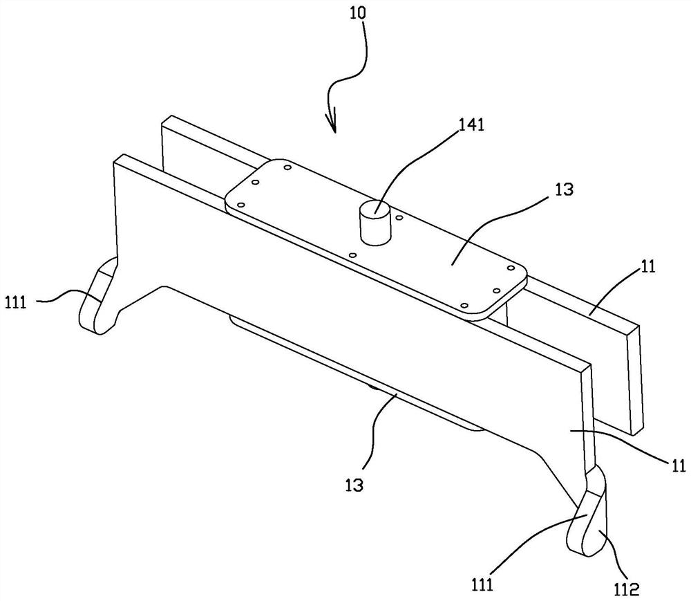
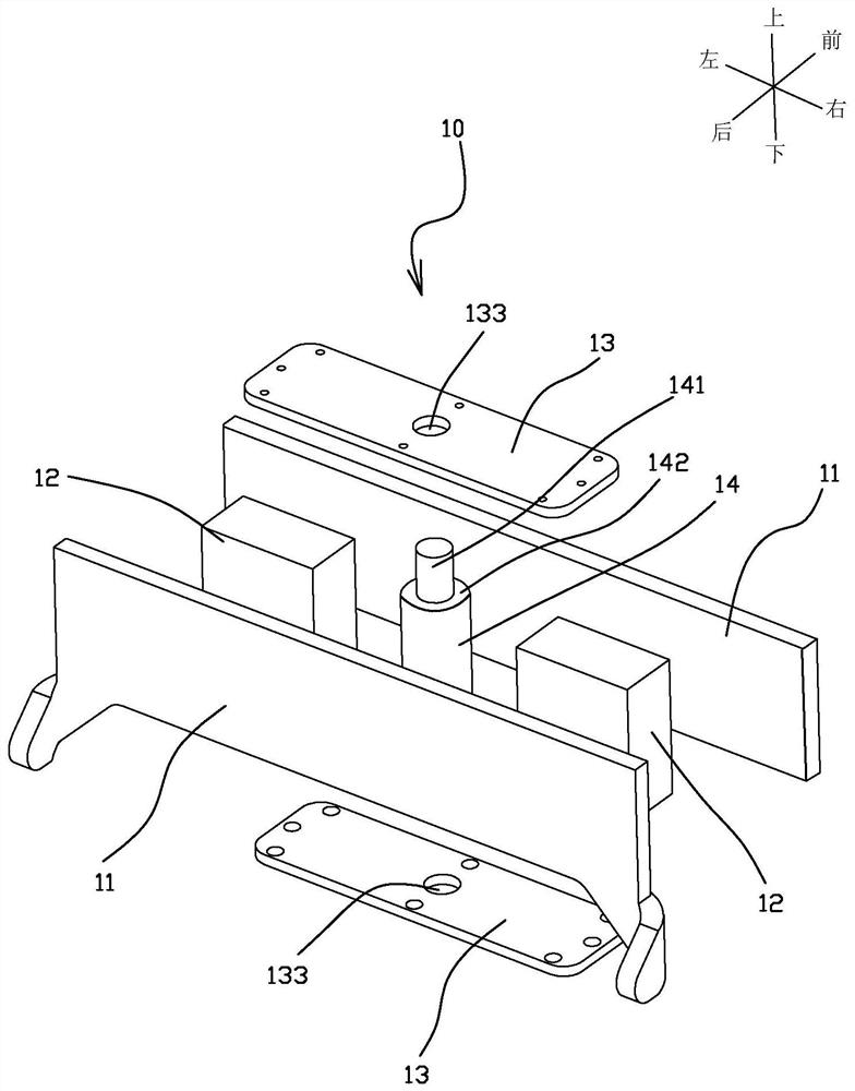
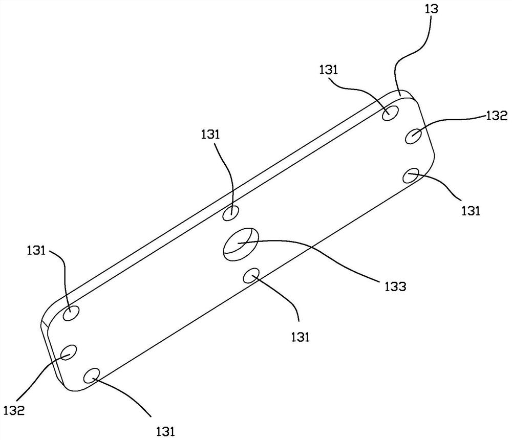
[0031] To further illustrate the various embodiments, the present invention is provided with accompanying drawings. These drawings are a part of the disclosure of the present invention, which are mainly used to illustrate the embodiments, and can be combined with related descriptions in the specification to explain the operating principles of the embodiments. With reference to these contents, those skilled in the art should understand other possible implementations and advantages of the present invention. Components in the figures are not drawn to scale, and similar component symbols are generally used to denote similar components.

[0032] It should be noted that in this article, descriptions with quantifiers such as "one..." or "two...", such as "one connecting shaft" and "two armatures" in the text, are used as quantities, which means one Connect the shaft, two armatures, etc. At the same time, the orientation words such as "front and back, left and right, up and down" de...


PUM


Abstract

The invention provides an armature assembly and a 1 / 2 crystal cover magnetic latching relay with the armature assembly. The armature assembly comprises two armatures, two pieces of magnetic steel, twopressing shaft pieces and a connecting shaft, wherein the two armatures are arranged in a front-back symmetrical mode, the two pieces of magnetic steel are arranged between the two armatures and distributed in a left-right spaced mode, and the two pole faces of the magnetic steel are tightly attached to the surfaces of the two armatures respectively; the two pressing shaft pieces are arranged onthe upper sides and the lower sides of the armatures respectively and fixedly connected with the two armatures; and the connecting shaft is arranged between the two pieces of magnetic steel, and the two ends of the connecting shaft penetrate through the two pressing shaft pieces respectively. The armature assembly forms a bridge-type double-armature structure and comprises two working air gaps, sothat the initial suction force of a magnetic circuit system of the relay is effectively improved, and the relay has good dynamic characteristics. Meanwhile, the structure has good symmetry, and the environmental resistance of the relay is effectively improved; and the problem that the retention force of the relay is asymmetric in self-holding and resetting states is solved, and the relay correction efficiency is effectively improved.

Description

technical field [0001] The invention relates to the field of relays, and specifically provides an armature assembly and a 1 / 2 crystal cover magnetic latching relay with the armature assembly. Background technique [0002] With the rapid development of aviation and aerospace technology, aerospace products tend to be miniaturized, miniaturized and intelligent. This makes the space for the signal control system very limited, and the volume of various components needs to be reduced as much as possible. The 1 / 2 crystal cover magnetic latching relay is produced under this background. [0003] The magnetic circuit structure of the existing 1 / 2 crystal cover magnetic latching relay generally adopts a differential structure, and the magnetic steel is in the form of three-stage magnetization (N-S-N or S-N-S), placed between the two yokes, and fixed by spot welding or laser welding; The armature part is located on the outer side of the magnetic circuit part, and can rotate around the...

Claims


Application Information

Patent Timeline
Patent Type & Authority Applications(China)
IPC IPC(8): H01H50/18H01H50/36
CPCH01H50/18H01H50/36
Inventor 郑春尧郑福基
Owner 厦门宏发密封继电器有限公司
Why Eureka
Try Eureka