Continuously variable transmission type variable fertilizer applicator

A technology of continuously variable transmission and fertilizer applicator, which is applied to fertilization devices, planting methods, fertilizer distributors, etc. It can solve the problems of limited fertilizer adjustment range, less research on mechanical continuously variable transmission, and inconvenient operation, so as to improve work efficiency. , Simple and compact structure, easy to operate

Pending Publication Date: 2020-12-29
SHIHEZI UNIVERSITY
View PDF0 Cites 2 Cited by
  • Summary
  • Abstract
  • Description
  • Claims
  • Application Information

AI Technical Summary

Problems solved by technology

[0003] The purpose of the present invention is to provide a continuously variable transmission type variable fertilizer applicator to solve the problem of limited range of adjustment of seed fertilizers, inconvenient operation and relatively poor research on mechanical continuously variable transmissions in the existing variable fertilization equipment proposed in the above technical background. In order to solve the problem, a cam-link mechanism is designed to be applied to a continuously variable transmission, and a cam-link continuously variable transmission is designed. The structure of the transmission is simple and compact, and the amount of fertilizer application can be adjusted without stopping the fertilizer applicator, which is easy to operate. , greatly improve the working efficiency of the fertilizer applicator, increase the utilization rate of chemical fertilizers, improve the farmland environment, increase the yield of crops, and increase the income of crops

Method used


Image

  • Continuously variable transmission type variable fertilizer applicator
  • Continuously variable transmission type variable fertilizer applicator
  • Continuously variable transmission type variable fertilizer applicator

Examples


Embodiment Construction

[0032] In order to make the purpose, technical solutions and advantages of the present invention clearer, the technical solutions in the present invention will be clearly and completely described below. Apparently, the described embodiments are part of the embodiments of the present invention, not all of them. Based on the embodiments of the present invention, all other embodiments obtained by persons of ordinary skill in the art without creative efforts fall within the protection scope of the present invention.

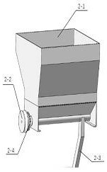
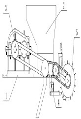
[0033] Such as figure 1 — Figure 10 As shown, a continuously variable transmission variable-variable fertilizer according to the present invention, its basic composition includes a frame, a fertilization mechanism, a variable speed transmission mechanism, a soil covering mechanism and a ditching mechanism.

[0034] further: as figure 2 As shown, in the frame 1, the motor mounting table 1-1 and the transmission mounting table 1-2 form the main body of the frame 1,...


PUM


Abstract

The invention relates to fertilizing machinery, in particular to a continuously variable transmission type variable fertilizer applicator. The fertilizer applicator mainly comprises five parts, namelya rack, a fertilizing mechanism, a variable speed transmission mechanism, a soil covering mechanism and a ditching mechanism. The rack comprises a motor mounting table, a speed changer mounting table, a fertilizing mechanism mounting frame, a soil covering mechanism mounting frame and a ditching mechanism mounting frame; the fertilizing mechanism mainly comprises a fertilizer discharging auger, afertilizer hopper and a fertilizer discharging pipe; the variable speed transmission mechanism mainly comprises a stepping motor and a gearbox, and the soil covering mechanism mainly comprises a soilcovering disc and a secondary adjusting rod; and the ditching mechanism mainly comprises a ditching cutter head and a ditching cutter. According to the fertilizer applicator, a single chip microcomputer and a GPS control the speed change of the stepping motor in real time, the change of the fertilizing amount is controlled in real time, the ditching mechanism ditches and fertilizes, then the soilcovering mechanism fills and levels up ditches, and all the parts are matched with one another to achieve the variable fertilizer discharging process.

Description

technical field [0001] The invention relates to the field of fertilizing machinery and equipment, in particular to a continuously variable transmission type variable fertilizing machine. Background technique [0002] For variable fertilization, we need to make reasonable use of chemical fertilizers, and the study of fertilization technology has very profound significance for the development of agriculture in our country. my country is a large agricultural country, and it is very necessary to implement variable fertilization. It can improve the utilization rate of fertilizers, improve the adverse effects of fertilizers on the environment, and make the economy and ecological environment develop in a high-quality direction. Due to the limited range of fertilizer adjustment, inconvenient operation, and less research on mechanical CVTs in my country's variable fertilization technology, a variable variable fertilizer with a CVT is proposed. The structure of the fertilizer applic...

Claims


Application Information

Patent Timeline
Patent Type & Authority Applications(China)
IPC IPC(8): A01C5/06A01C15/12
CPCA01C5/064A01C5/066A01C15/12
Inventor 胡雪郑雄飞买春亮蒋云
Owner SHIHEZI UNIVERSITY
Why Eureka
Try Eureka