Protection device for crop planting

A protection device and technology for crops, applied in plant protection, plant protection covers, devices for catching or killing insects, etc. The effect of high water and work efficiency

Inactive Publication Date: 2020-12-29
王连刚
View PDF7 Cites 0 Cited by
  • Summary
  • Abstract
  • Description
  • Claims
  • Application Information

AI Technical Summary

Problems solved by technology

[0004] 1. The existing thermal insulation devices for crops mainly use greenhouses for thermal insulation. Although the thermal insulation effect of greenhouses is good, it is laborious to build, and it is also very laborious to dismantle the greenhouses. Some crops need to be continuously built and maintained as the seasons change. Dismantling the greenhouse will cause a lot of work for the farmers;
[0005] 2. The traditional watering of crops or spraying pesticides is generally done manually, especially spraying pesticides, which requires people to shuttle back and forth in the crop planting fields to spray pesticides. This working method not only requires manual carrying of heavy cartridges , and it is easy to trample the crops to death;
[0006] 3. The traditional crop protection device does not have the function of storage. If it needs to be used, it needs to be installed at the target location. If it is not used, it needs to be disassembled and moved back to the warehouse. The installation and disassembly are not only troublesome, but also easy to cause damage to the device due to multiple installation and disassembly

Method used


Image

  • Protection device for crop planting
  • Protection device for crop planting
  • Protection device for crop planting

Examples


Embodiment 1

[0039] Such as Figure 1-12 shown;

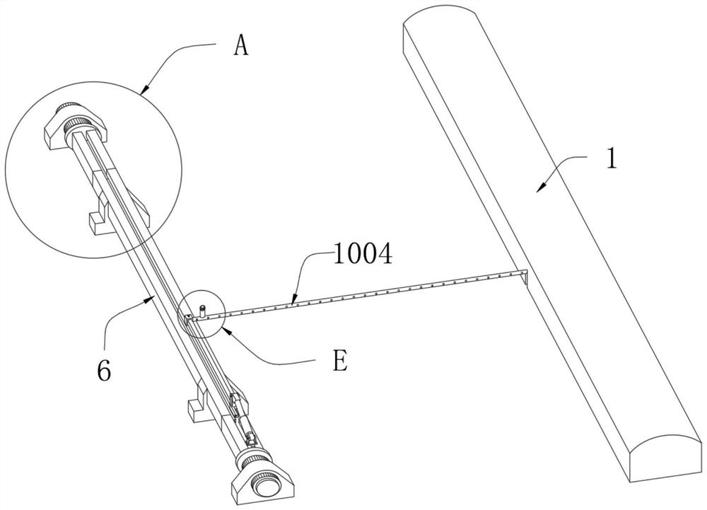
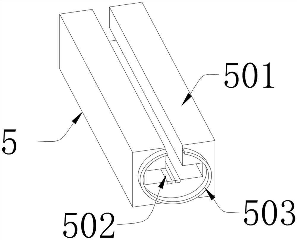
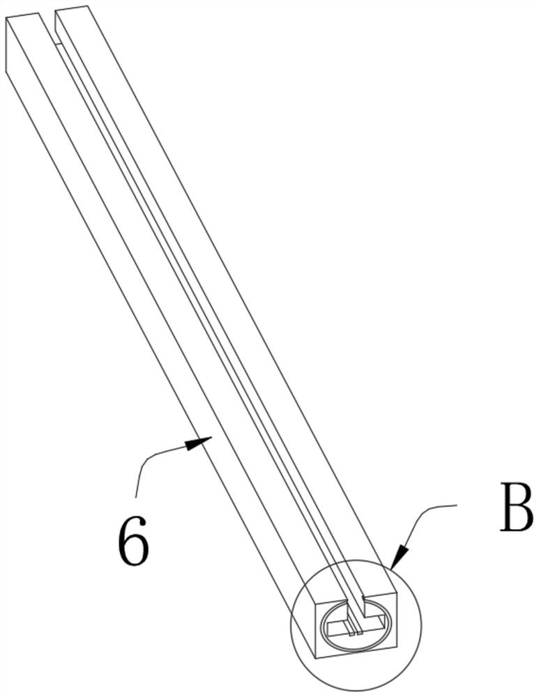
[0040]A protective device for planting crops, comprising a plastic dust cover 1 and a motor fixing bracket 2, a waterproof motor 3 is fixedly installed on the inner side of one end of the motor fixing bracket 2, a fixed turntable 4 is fixedly connected to the end of the main shaft of the waterproof motor 3, and the fixed turntable 4 The outer side of one end of the rotating slide rail assembly 5 is fixedly connected with the rotating slide rail assembly 5. The rotating slide rail assembly 5 includes a rotating slide rail base body 501, a first conductive strip 502, and a circular convex ring 503. There is a fixed slide rail assembly 6, which includes a fixed slide rail base 601, a second conductive strip 602, and a circular groove 603, and a slide rail fixing bracket is fixedly installed on the outside of one end of the fixed slide rail assembly 6 7. One end of the slide rail fixing bracket 7 is provided with a bracket notch 8, and the inn...


PUM


Abstract

The invention belongs to the technical field of crop planting, and particularly relates to a protection device for crop planting. The device comprises a plastic dustproof cover and a motor fixing support; a waterproof motor is fixedly installed at the inner side of one end of the motor fixing support; a fixing rotary disc is fixedly connected with the tail end of a main shaft of the waterproof motor; a rotary sliding rail assembly is fixedly connected with the outer side of one end of the fixing rotary disc; a fixed sliding rail assembly is rotatably connected with the outer side of one end ofthe rotary sliding rail assembly; a sliding rail fixing support is fixedly installed at the outer side of one end of the fixed sliding rail assembly; a support unfilled corner is arranged at one endof the sliding rail fixing support; an electric sliding device is connected with the inner side of of one end of rotary sliding rail assembly in a sliding mode; and a mounting head assembly is fixedlymounted at the outer side of the tail end of a rotary supporting rod. The protection device for crop planting has the function of automatically and rapidly spraying pesticide or watering; and a waterspraying pipe moves on the upper side of crops, and pesticide spraying or watering is conducted through the water spraying pipe, so that rapid pesticide spraying or watering can be realized.

Description

technical field [0001] The invention belongs to the technical field of crop planting, and in particular relates to a protective device for planting crops. Background technique [0002] Crops are all kinds of plants cultivated in agriculture, including food crops and economic crops (oil crops, vegetable crops, flowers, grass, trees). Only a proper diet can bring health to human beings. The growth of crops is inseparable from scientific and technological production technologies, as well as machinery and equipment manufactured by new industries that can assist agricultural production. [0003] There are following problems in existing technology: [0004] 1. The existing thermal insulation devices for crops mainly use greenhouses for thermal insulation. Although the thermal insulation effect of greenhouses is good, it is laborious to build, and it is also very laborious to dismantle the greenhouses. Some crops need to be continuously built and maintained as the seasons change. ...

Claims


Application Information

Patent Timeline
IPC IPC(8): A01G13/02A01G9/16A01G9/24A01M7/00
CPCA01G9/16A01G9/247A01G13/0206A01M7/0042Y02A40/25
Inventor 王连刚刘淑芹刘爱娜张永志赖永梅
Owner 王连刚
Why Eureka
Try Eureka