Driving shaft fixing and machining tool for mechanical part machining

A technology for mechanical parts and drive shafts, applied in the field of drive shaft processing tooling, can solve the problems of waste of adjustment time, bumping and wearing of the drive shaft, and inability to realize the auxiliary bearing of the drive shaft.

Active Publication Date: 2020-12-29
瑞安市祥晟汽车部件有限公司
View PDF23 Cites 0 Cited by
  • Summary
  • Abstract
  • Description
  • Claims
  • Application Information

AI Technical Summary

Problems solved by technology

[0007] In order to solve the above-mentioned technical problems, the present invention provides a drive shaft fixed processing tool for mechanical parts processing, to solve the existing problem that when the existing device clamps the drive shaft, it first needs to adjust the clamping seat to It is larger than the diameter of the drive shaft, which leads to a waste of adjustment time; moreover, the existing device cannot realize the auxiliary bearing of the drive shaft when placing the drive shaft, and it is easy to cause bumping and wear of the drive shaft when placing the drive shaft; finally Yes, the existing device cannot realize the reciprocating grinding of the marking part of the drive shaft through structural improvement, and the problem of automatic feeding of the grinding structure

Method used


Image

  • Driving shaft fixing and machining tool for mechanical part machining
  • Driving shaft fixing and machining tool for mechanical part machining
  • Driving shaft fixing and machining tool for mechanical part machining

Examples


Embodiment

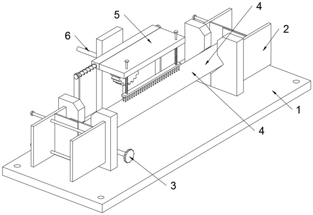
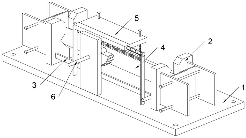
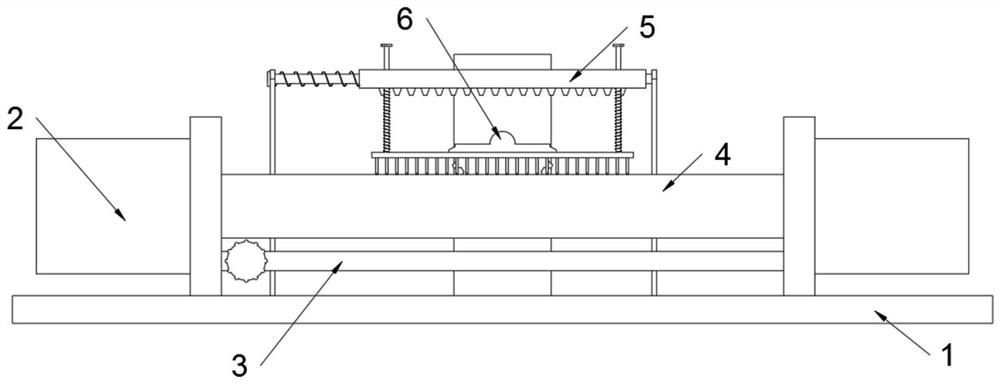
[0035] as attached figure 1 to attach Figure 8 Shown:

[0036] The present invention provides a driving shaft fixed processing tool for processing mechanical parts, including a base 1; two clamp structures 2 are installed on the base 1, and an adjustment structure 3 is installed on the clamp structure 2, and the clamp structure 2 is clamped There is a driving shaft 4; a grinding structure 5 is installed on the base 1, and a driving structure 6 is also installed on the base 1; refer to as Figure 5 with Image 6 , the fixture structure 2 includes a rectangular block 20101 and a rectangular groove 20501, the rectangular block 20101 is welded on the fixed fixture seat 201; the rectangular groove 20501 is opened on the movable fixture seat 205; The rectangular slot 20501 is plugged and connected, and the rectangular block 20101 and the rectangular slot 20501 together form the receiving structure when the driving shaft 4 is placed, thereby improving the convenience of placing t...


PUM


Abstract

The invention provides a driving shaft fixing and machining tool for mechanical part machining, and relates to the technical field of driving shaft machining tools. The problems that when a driving shaft is clamped, a clamping seat needs to be adjusted to be larger than the diameter of the driving shaft, auxiliary bearing of the driving shaft cannot be achieved, and collisions and abrasion of thedriving shaft are easily caused when the driving shaft is placed; and reciprocating type polishing of a coding part of the driving shaft cannot be achieved through structural improvement, and automatic feeding of a polishing structure cannot be achieved are solved. The driving shaft fixing and machining tool for mechanical part machining comprises a base. Two clamp structures are mounted on the base. Rectangular blocks are welded to fixed clamp seats; rectangular grooves are formed in movable clamp seats; and the rectangular blocks are matched with the rectangular grooves, the rectangular blocks and the rectangular grooves are connected in an inserted mode, and the rectangular blocks and the rectangular grooves jointly form a bearing structure when the driving shaft is placed.

Description

technical field [0001] The invention belongs to the technical field of drive shaft processing tooling, and more specifically relates to a drive shaft fixing tooling used for machining mechanical parts. Background technique [0002] The driving shaft is a kind of working device of the loader. It is a device that can push the smoothness of the loader so that the driving wheel can rotate according to different angular speeds. The driving shaft needs to be coded after processing, and the coded The location needs to be polished. [0003] For example, the application number: CN201410701705.6, the invention discloses a driving shaft drilling tool, including a support seat, a clamping part, a positioning seat and a clamping part; the clamping part can move on the support seat with a single degree of freedom through the guide groove , the clamping part is connected with the support seat through the shaft hole, and is connected with the clamping part through the guide groove at the s...

Claims


Application Information

Patent Timeline
Patent Type & Authority Applications(China)
IPC IPC(8): B24B41/06B24B5/04B24B5/35
CPCB24B5/04B24B5/35B24B41/06
Inventor 叶珊珊
Owner 瑞安市祥晟汽车部件有限公司
Why Eureka
Try Eureka