A multi-nozzle glaze spraying robot

A multi-nozzle and robot technology, applied in the field of robotics, can solve the problems of reducing the diameter of the spray gun, harm, and reducing the mist output of the glaze, so as to ensure the mist output and speed up the flow speed.

Active Publication Date: 2021-11-16
NANJING RUIQI ELECTRONICS TECH CO LTD
View PDF11 Cites 0 Cited by
  • Summary
  • Abstract
  • Description
  • Claims
  • Application Information

AI Technical Summary

Problems solved by technology

[0002] Glaze spraying is an important process in the production process of ceramic products. It is realized by using compressed air to spray the glaze slurry through the spray gun to form a mist spray glaze on the product body. The glaze spraying robot replaces manual spraying of the product. The glaze spraying robot can adapt to spray The high temperature, high humidity, and dusty environment at the glaze site can reduce the health hazards of workers in a dusty environment. However, when spraying glaze on products, in order to increase the adhesion between glaze slurry and product body Due to the increase in the thickness of the glaze slurry, when the spray gun on the glaze spraying robot finishes spraying glaze, part of the glaze slurry stays inside the nozzle and spray gun, and the inside of the glaze slurry The gas is difficult to discharge, and the glaze slurry is easy to condense inside the nozzle and spray gun to form agglomerates, resulting in the reduction of the caliber of the spray gun and reducing the amount of mist for the next glaze spraying

Method used


Image

  • A multi-nozzle glaze spraying robot
  • A multi-nozzle glaze spraying robot
  • A multi-nozzle glaze spraying robot

Examples


Embodiment 1

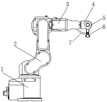
[0026] as attached figure 1 to attach Figure 5 Shown:

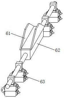
[0027] The present invention is a kind of multi-nozzle spraying glaze robot, and its structure comprises supporting base 1, rotating arm 2, supporting arm 3, rotating shaft 4, supporting plate 5, spraying glaze mechanism 6, spraying glaze conduit 7, described supporting base 1 top and The lower end of the rotating arm 2 is axially connected, the upper end of the rotating arm 2 is axially connected with the left end of the supporting arm 3, the front end of the supporting arm 3 is provided with a rotating shaft 4, and the rotating shaft 4 is axially connected with the upper end of the supporting plate 5, and the supporting plate 5 The lower end is welded to the upper end of the glaze spraying mechanism 6, and the right end of the glaze spraying conduit 7 is embedded and installed with the glaze spraying mechanism 6. The glaze spraying mechanism 6 includes a connecting frame 61, a glaze storage box 62, and a multi-nozzle ...

Embodiment 2

[0034] as attached Figure 6 to attach Figure 9 Shown:

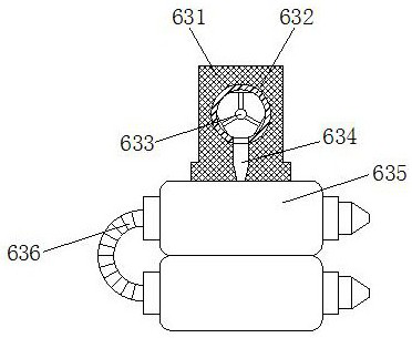
[0035] Wherein, the anti-blocking nozzle 635 includes a spray chamber 35a, a swing mechanism 35b, a left outlet groove 35c, a right outlet groove 35d, and a nozzle 35e. The lower end is provided with a swing mechanism 35b, the inner left end of the spray chamber 35a is provided with a left outlet groove 35c, and the inner right end of the spray chamber 35a is provided with a right outlet groove 35d, and the outside of the right end of the spray chamber 35a is fixedly equipped with a nozzle 35e. A spring is also provided at the lower end of the mechanism 35b, and the elastic force of the spring makes the swing mechanism 35b swing left and right to speed up the flow speed of the glaze slurry, and less glaze slurry stays inside the spray chamber 35a.

[0036] Wherein, the swing mechanism 35b includes a swing plate b1, a leak-proof plate b2, a hinge shaft b3, a left runner b4, and a right runner b5. The inner wall of the...


PUM


Abstract

The invention discloses a multi-nozzle glaze spraying robot, the structure of which comprises a supporting base, a rotating arm, a supporting arm, a rotating shaft, a supporting plate, a glaze spraying mechanism, a glaze spraying conduit, the top of the supporting base is axially connected with the lower end of the rotating arm, and the glaze slurry During the flow process, the connecting block rotates inside the nozzle. At this time, the spring on the connecting plate ejects the glaze slurry and crushes the particles inside the glaze slurry. At the same time, the connecting block drives the scraper inside the nozzle. Rotate in a circle to scrape the remaining glaze slurry on the inner wall of the nozzle to ensure that all the glaze slurry is discharged to the through hole. The glaze slurry flows into the spray chamber through the through hole, and the gravity of the glaze slurry makes the swing plate swing left and right to speed up. The flow speed of the glaze slurry is less, the glaze slurry stays inside the spray chamber. During the spraying process, the inclined burrs pierce the air bubbles in the glaze slurry to ensure that the gas inside the glaze slurry is discharged and prevent the glaze slurry from being sprayed in the nozzle. Internal condensation forms agglomerates to ensure the fog output of the nozzle spray glaze.

Description

technical field [0001] The invention relates to the field of robots, and more specifically relates to a multi-nozzle glaze spraying robot. Background technique [0002] Glaze spraying is an important process in the production process of ceramic products. It is realized by using compressed air to spray the glaze slurry through the spray gun to form a mist spray glaze on the product body. The glaze spraying robot replaces manual spraying of the product. The glaze spraying robot can adapt to spray The high temperature, high humidity, and dusty environment at the glaze site can reduce the health hazards of workers in a dusty environment. However, when spraying glaze on products, in order to increase the adhesion between glaze slurry and product body Due to the increase in the thickness of the glaze slurry, when the spray gun on the glaze spraying robot finishes spraying glaze, part of the glaze slurry stays inside the nozzle and spray gun, and the inside of the glaze slurry The...

Claims


Application Information

Patent Timeline
Patent Type & Authority Patents(China)
IPC IPC(8): B05B15/52B28B11/04B28B17/00B25J11/00B05B15/50B02C13/04B02C13/28B01D19/00B01D19/02
CPCB01D19/0073B01D19/02B02C13/04B02C13/28B25J11/0075B28B11/044B28B11/048B28B17/00B05B15/50
Inventor 何金花
Owner NANJING RUIQI ELECTRONICS TECH CO LTD
Why Eureka
Try Eureka