
A connection structure between a suspended monorail and a road bridge cover beam

A technology for highway bridges and connecting structures, applied in bridges, bridge construction, bridge parts, etc., can solve problems such as insufficient bearing capacity of joints, weakening of flange plate bearing capacity, inconvenient construction process, etc., and achieve reliable and effective mechanical performance Guaranteeing and increasing bridge space utilization, and the effect of simple and clear force transmission path

Active Publication Date: 2021-11-09
TONGJI UNIV
View PDF0 Cites 0 Cited by
  • Summary
  • Abstract
  • Description
  • Claims
  • Application Information

AI Technical Summary

Problems solved by technology

[0007] Although each of the above-mentioned schemes has the possibility of realization in theory, the above-mentioned schemes do not involve the cover beam in the design, but only set the connection in the bridge deck, and there is a weakening of the bridge superstructure or the track beam by the connection structure effect
In addition, each scheme also has its own shortcomings
[0008] The main defect of the first connection method and structure is that the hollow steel pipe will occupy a large space inside the flange plate, which will affect the reinforcement inside the flange plate and thus affect the bearing capacity of the flange plate. The bonding force between the steel pipe and the flange plate is mainly realized by the corbel column on its side, which may cause the problem of insufficient bearing capacity
In addition, the construction of this connection structure is also inconvenient. It is necessary to weld the hollow steel pipe and the suspension components and place them in the flange plate and pour them at the same time, which may cause the concrete to not be compacted by vibration, and the construction process is also inconvenient.
[0009] The main defect of the second connection method is that the penetrating high-strength bolts connect the L-shaped plate. On the one hand, it is required that the thickness of the flange plate should not be too large, which is in contradiction with the fact that the flange plate needs a higher bearing capacity; on the other hand The opening of the bolt holes will further weaken the bearing capacity of the flange plate, and if the compaction work is not done well, it is easy to cause the bolts to corrode and affect the bearing capacity
In addition, high-strength bolts need to have sufficient bearing capacity, which requires a sufficient number of bolts, which will cause further contradictions of the aforementioned problems, so the applicable range in practical applications is relatively small
[0010] The main defect of the third combined connection method is that the suspension track not only has corrugated steel plates, but also has concrete wrapped on both sides, resulting in a large dead weight, high requirements for the bolted connection of the upper floor, and may also cause insufficient bearing capacity at the connection. Case

Method used


Image

  • A connection structure between a suspended monorail and a road bridge cover beam
  • A connection structure between a suspended monorail and a road bridge cover beam
  • A connection structure between a suspended monorail and a road bridge cover beam

Examples


Embodiment

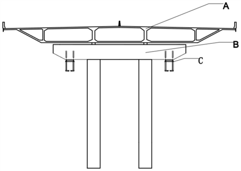
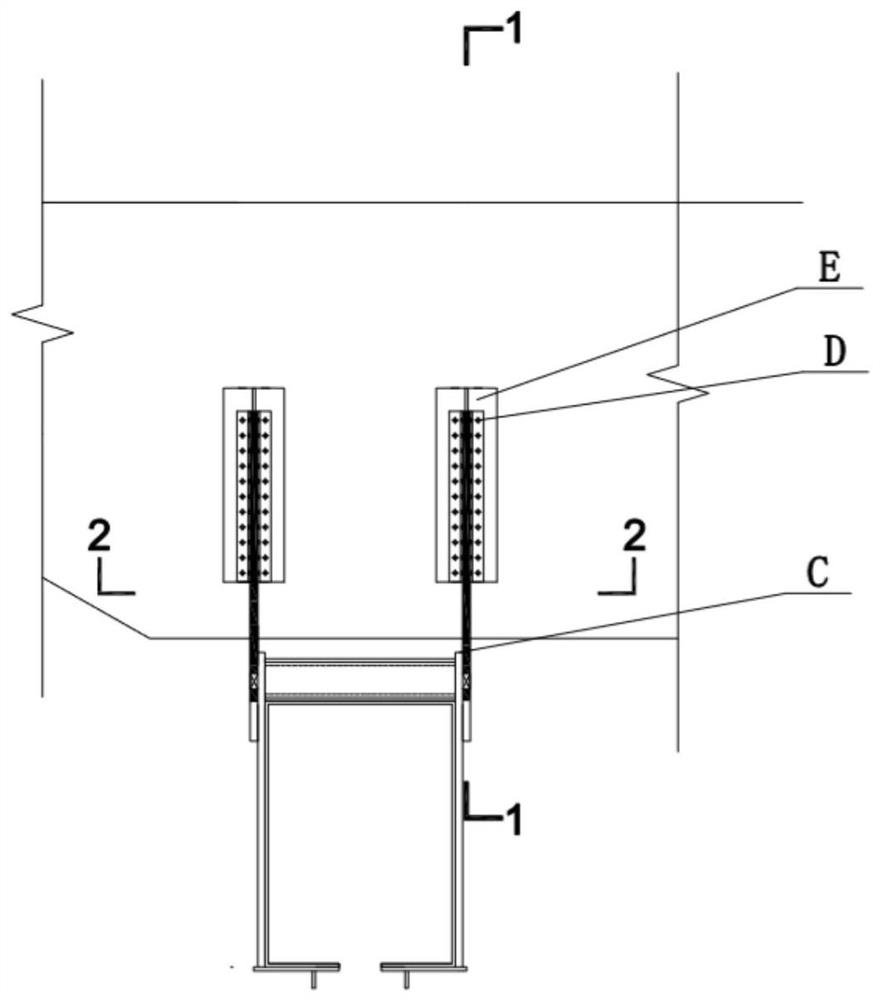
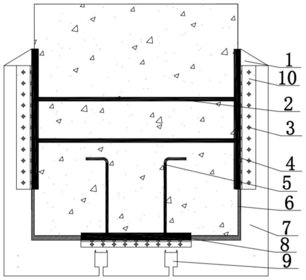
[0037] Such as Figure 1 to Figure 4 As shown, the present invention relates to a connection structure between a suspended monorail and a highway bridge cover beam, which is used for stably connecting the highway bridge cover beam and the suspended monorail, increasing the space utilization rate of the bridge, and relieving traffic pressure. The structure mainly includes reserved part E and connecting part D. The highway bridge box girder plate A is used to bear the upper part of the vehicle lane load bridge superstructure, which belongs to the prior art and will not be described in detail. The transition component cover beam B is installed at the bottom of the box girder slab A of the highway bridge, and is used to transfer the load of the vehicle lane to the bridge pier, and is also used to bear the self-weight of the suspended track beam C. The suspended track beam C is arranged at the bottom of the transition member cover beam B.

[0038] Transition member cover beam B i...


PUM


Abstract

The invention relates to a connection structure between a suspended monorail and a highway bridge cover beam, which comprises a highway bridge box girder plate, a transition component cover beam and a suspended track beam connected sequentially from top to bottom, and the transition component cover beam passes through the Install the reserved part and the connecting part to connect with the suspended track beam. The reserved part includes the reserved floor at the inner bottom of the cover beam of the transition member, the reserved side plate of the inner wall, and the steel skeleton arranged inside the cover beam of the transition member The reserved side plate on the upper side is connected to the tensile steel bar and the reserved bottom plate is pulled out. The bottom is hinged to the top of the suspended track beam. Compared with the prior art, the present invention has the advantages of increasing the space utilization rate of the bridge, alleviating traffic pressure, convenient and fast construction, and the like.

Description

technical field [0001] The invention relates to the technical field of suspended rail transit, in particular to a connection structure between a suspended monorail and a road bridge cover beam. Background technique [0002] With the development of modern society, people's pace of life is getting faster and faster, resulting in increasing pressure on the ground transportation system, which in turn reduces the usable transportation space on the ground. Due to the increasing investment in underground space development, people urgently need some new traffic systems to relieve traffic pressure. The suspended rail transit system built together with the elevated road is to use the characteristics of the suspended rail set above the train, combine the suspended rail train with the elevated road, and use the redundant space under the bridge of the elevated road to relieve the traffic pressure on the ground . [0003] Suspended monorails have been developed and put into use abroad i...

Claims


Application Information

Patent Timeline
Patent Type & Authority Patents(China)
IPC IPC(8): E01B25/24E01B25/22E01D19/00
CPCE01B25/22E01B25/24E01D19/00
Inventor 吴雨潇李奇肖清华卢秉涵
Owner TONGJI UNIV
Learn More