Supercharge Your Innovation With Domain-Expert AI Agents!

Three-dimensional deployment system for fracturing well site

A deployment system and fracturing well technology, which is applied in the field of three-dimensional deployment system for fracturing well sites, can solve problems such as unintuitive data, inability to accurately grasp real-time dynamic data of equipment, and prediction and evaluation of failure causes, so as to improve construction quality and improve construction quality. The effect of information level

Pending Publication Date: 2020-12-29
四机赛瓦石油钻采设备有限公司
View PDF6 Cites 3 Cited by
  • Summary
  • Abstract
  • Description
  • Claims
  • Application Information

AI Technical Summary

Problems solved by technology

[0003] In order to overcome the above-mentioned defects of the prior art, the present invention provides a fracturing well site three-dimensional deployment system. The technical problem to be solved by the present invention is: the cause of the fault cannot be predicted and evaluated according to the fault information that occurs, and it is necessary to visit the site in person Stopping the equipment and dismantling it for inspection cannot quickly and accurately determine the cause of the failure, which affects the construction efficiency; during the operation, the real-time dynamic data of the equipment cannot be accurately grasped, and there is no accurate real-time data support for the well under the current working conditions. Assess the overall situation of the field and take corresponding measures, the data is not intuitive, dynamic, and cannot be visualized, and the scene information of the operating equipment, equipment operating parameters, and alarm status cannot be quickly and comprehensively displayed, which is not conducive to the construction of the fracturing well site.

Method used


Image

  • Three-dimensional deployment system for fracturing well site

Examples


Embodiment Construction

[0023] The following will clearly and completely describe the technical solutions in the embodiments of the present invention with reference to the accompanying drawings in the embodiments of the present invention. Obviously, the described embodiments are only some, not all, embodiments of the present invention. Based on the embodiments of the present invention, all other embodiments obtained by persons of ordinary skill in the art without making creative efforts belong to the protection scope of the present invention.

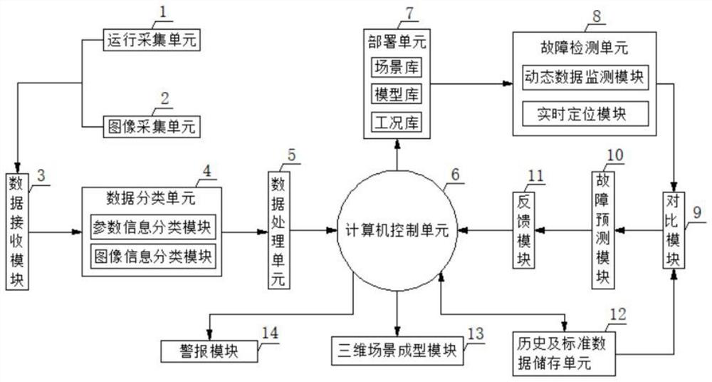
[0024] As shown in the figure, the present invention provides a three-dimensional deployment system for fracturing well sites, including an operation acquisition unit 1 and an image acquisition unit 2, the output ends of the operation acquisition unit 1 and the image acquisition unit 2 are connected to the input of the data receiving module 3 Terminal electrical connection, operation acquisition unit 1 is composed of sensors and acquisition modules, and collect...


PUM


Abstract

The invention discloses a three-dimensional deployment system for a fracturing well site, and particularly relates to the technical field of fracturing well site construction. The three-dimensional deployment system comprises an operation acquisition unit and an image acquisition unit, wherein the output ends of the operation acquisition unit and the image acquisition unit are electrically connected with the input end of a data receiving module. According to the three-dimensional deployment system, the operation acquisition unit, the image acquisition unit, a data processing unit, a computer control unit, a deployment unit, a dynamic data monitoring module and a three-dimensional scene forming module are matched, a scene library, a model library, a working condition library and the dynamicdata monitoring module which are matched are used for interpreting, comparing and analyzing one by one, well site characteristics are identified and then rendered, and a three-dimensional well site is drawn through the three-dimensional scene forming module; and meanwhile, operation parameters and alarm information of equipment are dynamically presented in real time so as to assist construction management personnel in mastering the actual condition of the well site, the construction quality and the informatization level of the fracturing well site are improved, and the construction work of the fracturing well site is facilitated.

Description

technical field [0001] The invention relates to the technical field of fracturing well site construction, and more specifically, the invention relates to a three-dimensional deployment system for fracturing well sites. Background technique [0002] In the construction of fracturing well sites, some equipment will inevitably have certain failures during use, and the cause of the failure cannot be predicted and evaluated based on the failure information. It is necessary to visit the site to shut down the equipment and disassemble it. inspection, it is impossible to quickly and accurately determine the cause of the fault, which affects the construction efficiency; because the equipment is frequently transferred, and the area, layout, construction process, working conditions, equipment configuration, device type, and quantity of each well site are not the same, often on-site The layout presentation is simple temporary presentation by hand drawing on the whiteboard, and the proje...

Claims


Application Information

Patent Timeline
Patent Type & Authority Applications(China)
IPC IPC(8): E21B43/26E21B47/00G06F30/13
CPCE21B43/26E21B47/00G06F30/13
Inventor 王传鸿李建新熊伟骆竖星李正勇黄河
Owner 四机赛瓦石油钻采设备有限公司
Features
  • R&D
  • Intellectual Property
  • Life Sciences
  • Materials
  • Tech Scout
  • Unparalleled Data Quality
  • Higher Quality Content
  • 60% Fewer Hallucinations
Learn More