
A double gate air lock wear-resistant valve

An air lock and valve body technology, applied in the field of wear-resistant valves, can solve problems such as the impact of wear-resistant valve sealing performance, and achieve the effect of improving air tightness

Active Publication Date: 2022-03-29
CHANGZHOU LONGJIN MASCH CO LTD
View PDF12 Cites 0 Cited by
  • Summary
  • Abstract
  • Description
  • Claims
  • Application Information

AI Technical Summary

Problems solved by technology

There are often gaps at the connection between the gate and the valve body cavity, and the liquid will flow into the valve body through the gaps, which will affect the sealing performance of the wear-resistant valve.
[0004] In view of the above-mentioned related technologies, the inventor believes that there are often gaps at the connection between the gate plate and the inner cavity of the valve body, and the liquid will flow into the valve body through the gaps, thereby affecting the sealing performance of the wear-resistant valve.

Method used


Image

  • A double gate air lock wear-resistant valve
  • A double gate air lock wear-resistant valve
  • A double gate air lock wear-resistant valve

Examples


Embodiment Construction

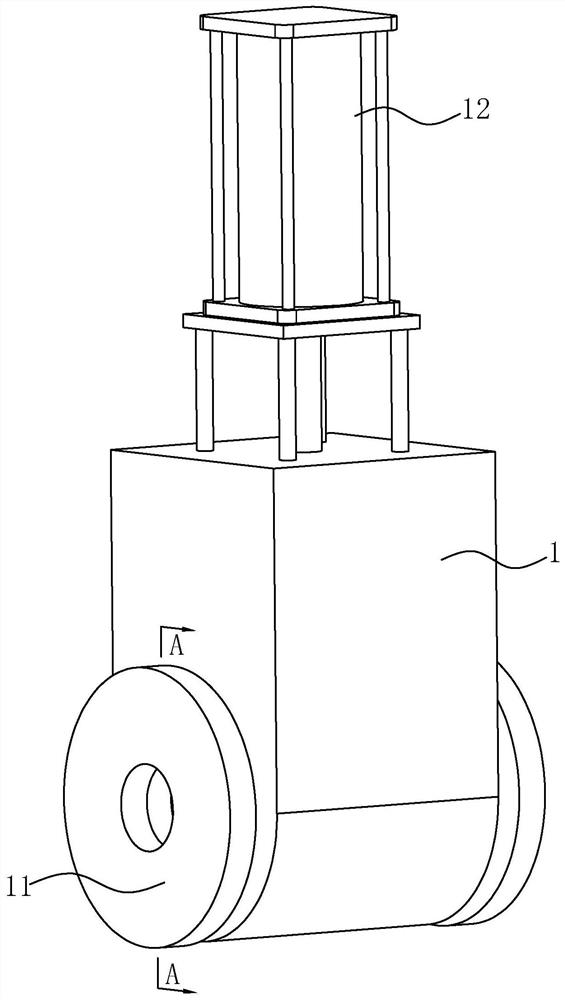
[0032] The following is attached Figure 1-4 The application is described in further detail.

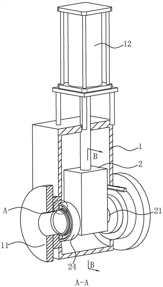
[0033] The embodiment of the application discloses a double-gate airlock wear-resistant valve. refer to figure 1 with figure 2 The wear-resistant valve includes a valve body 1 , water inlet pipes 11 fixed on both sides of the valve body 1 and a cylinder 12 fixed on the top of the valve body 1 . The bottom end of the hydraulic rod of the cylinder 12 is fixed with a control box 2 , and a valve shaft 21 is installed through the control box 2 ; the valve shaft 21 is connected to the control box 2 in rotation.

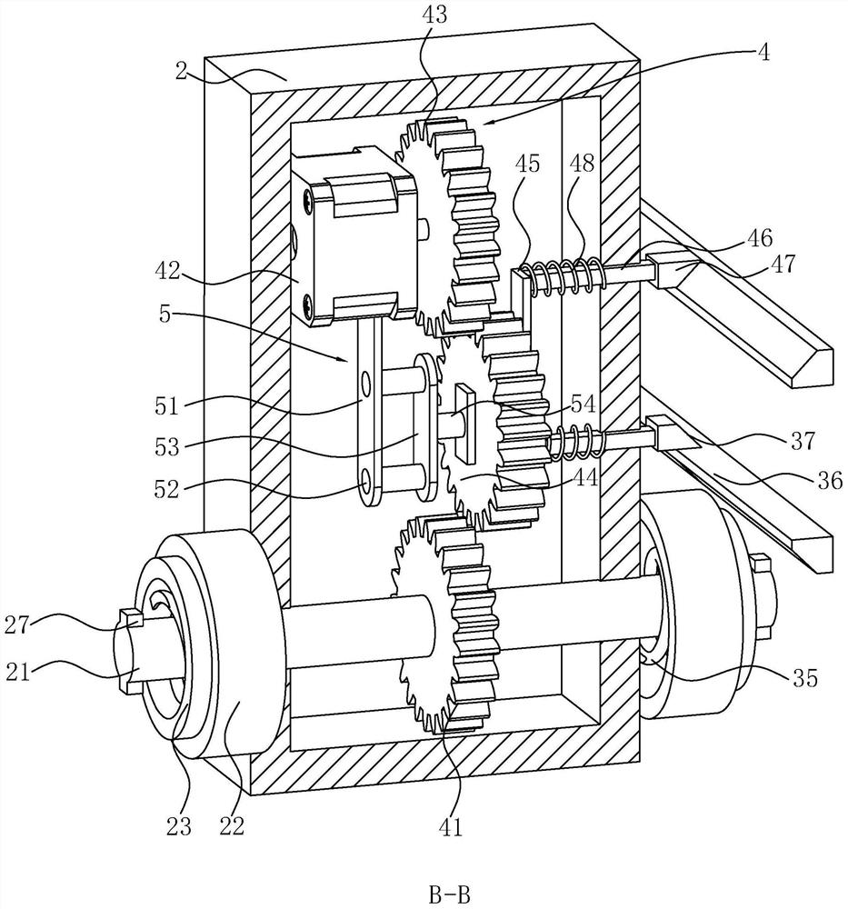
[0034] refer to figure 2 with image 3 , the two sides of the control box 2 are respectively fixed with tail pipes 22, and the two tail pipes 22 are respectively provided with telescopic pipes 23 sliding along the length direction of the control box 2. A valve plate 24 is respectively fixed on the side of each telescopic tube 23 away from the control box 2 . The side of t...


PUM


Abstract

The application relates to a double-gate air-lock wear-resistant valve, which comprises a valve body, water inlet pipes fixed on both sides of the valve body, and a cylinder fixed on the top of the valve body; a control box is fixed at the bottom end of a hydraulic rod of the cylinder, and the control box A valve shaft is arranged through the inside; the valve shaft is rotatably connected with the control box; the outer peripheral surface of the valve shaft is slidingly connected with two valve plates along the axial direction of the valve shaft; a first spring is fixed on the side of the valve plate close to the control box, and the first spring is far away from the control box. One end of the valve plate is fixedly connected to the side of the control box close to the valve plate. The present application has the effect of improving the sealing performance of the wear-resistant valve gate.

Description

technical field [0001] The present application relates to the field of wear-resistant valves, in particular to a double-gate airlock wear-resistant valve. Background technique [0002] At present, wear-resistant valves refer to valves with wear-resistant butterfly plates. The wear-resistant valve is composed of a pneumatic actuator and a butterfly valve. The actuator is the main body, and the air source signal pressure output by the pneumatic element is used as the power. The air flow direction is changed through the control element to control the opening and closing of the valve. [0003] Related technologies can refer to the Chinese invention patent application with the publication number CN109027282A, which discloses a cast steel flat gate valve with a double gate valve, which includes a valve body. Flanges are respectively arranged on both sides of the valve body. gate. The front and rear end surfaces of each gate are provided with arc-shaped grooves, and the inner cav...

Claims


Application Information

Patent Timeline
Patent Type & Authority Patents(China)
IPC IPC(8): F16K3/18F16K3/30F16K3/314F16K27/04F16K31/12F16K31/04F16K31/53F16K31/46
CPCF16K3/18F16K3/30F16K3/314F16K27/044F16K31/12F16K31/043F16K31/53F16K31/46
Inventor 刘光明殷渊强佳新
Owner CHANGZHOU LONGJIN MASCH CO LTD
Learn More