
Valve core displacement-variable control device for construction machinery

A technology of spool displacement and construction machinery, which is applied in the direction of valve device, non-electric variable control, valve operation/release device, etc. It can solve problems such as unstable circuit pressure, affecting the stability of hydraulic circuit, and inconvenient detection.

Inactive Publication Date: 2020-12-29
武汉艾络特科技有限公司
View PDF10 Cites 0 Cited by
  • Summary
  • Abstract
  • Description
  • Claims
  • Application Information

AI Technical Summary

Problems solved by technology

[0005] In order to solve the above technical problems, the present invention provides a variable valve core displacement control device for construction machinery to solve the problem that the circuit pressure controlled by the hydraulic control valve in the above patent is not constant, it is inconvenient to detect, and it is not convenient to control the pressure inside the hydraulic circuit As well as the flow rate, when the output power of the hydraulic motor is unstable, it will affect the overall stability of the hydraulic circuit

Method used


Image

  • Valve core displacement-variable control device for construction machinery
  • Valve core displacement-variable control device for construction machinery
  • Valve core displacement-variable control device for construction machinery

Examples


Embodiment

[0035] as attached figure 1 to attach Figure 10 Shown:

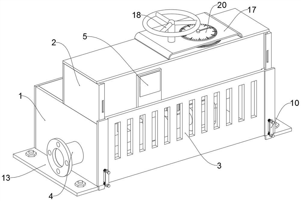
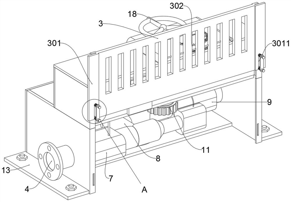
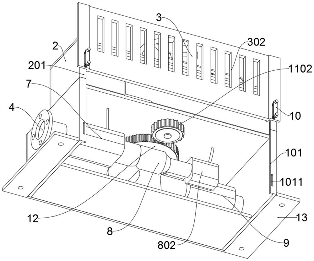
[0036]The invention provides a valve core displacement variable control device for construction machinery, which includes a lower protective frame 1, a heat dissipation plate 3, a liquid inlet 4, a display screen 5, a transmission pipe 8, a pressure detector 9, an adjustment switch 10, and a transmission Part 11, adjusting gear 12, mounting seat 13, controller 15, valve body 16, upper shell cover 17, hand wheel 18, driven metering wheel 19, metering disc 20; the upper surface of the lower protective frame 1 is connected by welding The lower surface of the protective frame 2; the cooling plate 3 is slidably connected to the front side of the lower protective frame 1 and the upper protective frame 2; the liquid inlet 4 passes through the left side plate of the lower protective frame 1 and is fixedly connected to the flow monitor 7; the transmission pipe The left side of 8 is fixedly connected to the right outlet of flow...


PUM


Abstract

The invention provides a valve core displacement-variable control device for construction machinery. The device comprises a lower protective frame, a heat dissipation plate, a liquid inlet end, a display screen, a conveying pipe, a second pressure detector, an adjusting switch, a transmission part, an adjusting gear, a mounting base, a controller, a valve body, an upper shell cover, a hand wheel,a driven metering wheel and a metering panel; the upper surface of the lower protective frame is connected to the lower surface of an upper protective frame in a welded mode; the heat dissipation plate is connected to the front sides of the lower protective frame and the upper protective frame in a sliding mode; the liquid inlet end penetrates through a left side plate of the lower protective frame to be fixedly connected to a flow monitor; the left side of the conveying pipe is fixedly connected to an outlet in the right side of the flow monitor; the input end of the second pressure detectoris fixedly connected to the right end of the conveying pipe, and the output end of the second pressure detector is fixedly connected to a liquid outlet end. a guide rod of the adjusting switch is fixedly connected to the surface of the heat dissipation plate; the detector can measure the hydraulic pressure and the flow of the valve body; and when the hydraulic pressure is unstable, a hydraulic loop is possibly influenced, and then the valve body can be controlled to be turned off.

Description

technical field [0001] The invention belongs to the technical field of mechanical spool control, and more specifically relates to a variable control device for spool displacement of construction machinery. Background technique [0002] In construction machinery, large-scale carrying equipment usually has an automatic unloading mechanism, which is generally realized by a hydraulic control system. The hydraulic valve is an automatic component operated by pressure oil. It is controlled by the pressure oil of the pressure distribution valve. It is usually used in combination with the electromagnetic pressure distribution valve. It can be used to remotely control the on-off of the oil, gas and water pipeline system of the hydropower station. Commonly used in clamping, control, lubrication and other oil circuits. There are direct-acting and pilot-operated types, and the pilot-operated type is often used. Common valves used in construction machinery can adjust the flow rate by adj...

Claims


Application Information

Patent Timeline
IPC IPC(8): F16K37/00F16K49/00F16K31/60F16K31/53G05D27/02
CPCF16K37/0091F16K49/00F16K31/60F16K31/535G05D27/02
Inventor 孟海涛
Owner 武汉艾络特科技有限公司
Learn More