Efficient wood drying device

A drying device and wood technology, applied in drying, drying machines, heating devices, etc., can solve the problems affecting drying efficiency and drying effect, applicability and practicability limitations, and the bottom surface of wood is damaged. , to achieve the effect of improving the drying effect, good practicability and improving efficiency

Inactive Publication Date: 2020-12-29
徐艳
View PDF0 Cites 0 Cited by
  • Summary
  • Abstract
  • Description
  • Claims
  • Application Information

AI Technical Summary

Problems solved by technology

[0002] Wood processing mainly includes basic processing such as wood cutting, wood drying and wood gluing. Corresponding drying equipment needs to be used during wood drying. The bearing plate, heating device and exhaust pipe can meet the needs of the market, but in the actual drying operation, because the bottom surface of the wood is attached to the bearing plate, it is difficult to dry the bottom surface during drying, while If the heating device is directly fixed on the bearing plate, the bottom surface of the wood will be directly contacted with the bearing plate, which will cause the bottom surface of the wood to be damaged, affect the quality of the wood, and thus affect the drying efficiency and drying effect, so the applicability and practicality is limited

Method used


Image

  • Efficient wood drying device

Examples


Embodiment 1

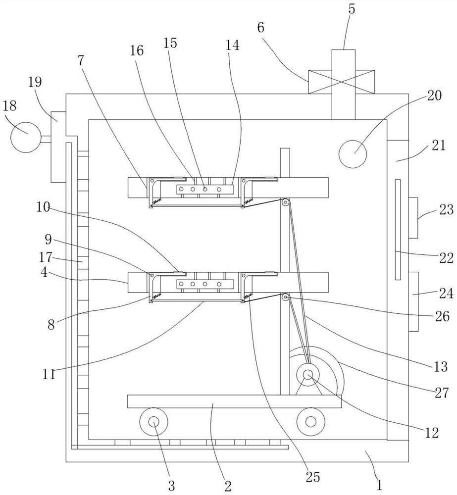
[0016] figure 1 A specific embodiment of the invention is shown in which figure 1 It is a structural schematic diagram of the present invention.

[0017] See figure 1 , a high-efficiency wood drying device, including a drying chamber 1, a drying rack 2 is arranged in the drying chamber, a walking wheel 3 is fixed on the bottom surface of the drying rack, and several A parallel drying carrier plate 4, an exhaust pipe 5 is fixed on the drying chamber, and a condenser 6 is connected to the exhaust pipe. In this embodiment, the condenser is a technical knowledge structure of the prior art , the top surface of the drying carrier plate is provided with at least two parallel strip-shaped grooves 7, and at least three strip-shaped grooves are provided, and wood of different lengths can be placed, thereby greatly improving the drying range. A seesaw 8 is arranged in the strip groove, the middle part of the seesaw is connected in the strip groove by a pin 9, a support plate 10 is fix...


PUM

PropertyMeasurementUnit
Widthaaaaaaaaaa

Abstract

The invention discloses an efficient wood drying device. The efficient wood drying device comprises a drying cavity, wherein a drying frame is arranged in the drying cavity, walking wheels are fixed to the bottom face of the drying frame, a plurality of parallel drying bearing plates are arranged on the drying frame, an exhaust pipe is fixed to the drying cavity, and a condenser is connected to the exhaust pipe. At least two parallel strip-shaped grooves are formed in the top faces of the drying bearing plates, warping plates are arranged in the strip-shaped grooves, the middles of the warpingplates are connected into the strip-shaped grooves through pin shafts, supporting plates are fixed to the top ends of the warping plates, the bottom ends of the warping plates are connected through synchronous supporting rods, and a winding motor is fixed to the bottom of the drying frame; and an inhaul cable is arranged between a main shaft of the winding motor and the bottom ends of the warpingplates, heating cavities are fixed in the drying bearing plates, and electric heating pipes are fixed in each heating cavity. According to the efficient wood drying device, the structural arrangementis reasonable, the situation that during drying, the bottom face of wood cannot be dried or is damaged due to contact is avoided, the drying efficiency and the drying effect can be better improved, and the efficient wood drying device is high in applicability and good in practicability.

Description

technical field [0001] The invention belongs to the technical field of wood processing equipment, and in particular relates to a high-efficiency wood drying device. Background technique [0002] Wood processing mainly includes basic processing such as wood cutting, wood drying and wood gluing. Corresponding drying equipment needs to be used during wood drying. The bearing plate, heating device and exhaust pipe can meet the needs of the market, but in the actual drying operation, because the bottom surface of the wood is attached to the bearing plate, it is difficult to dry the bottom surface during drying, while If the heating device is directly fixed on the bearing plate, the bottom surface of the wood will be directly contacted with the bearing plate, which will cause the bottom surface of the wood to be damaged, affect the quality of the wood, and thus affect the drying efficiency and drying effect, so the applicability and practicality is limited. Contents of the inve...

Claims


Application Information

Patent Timeline
IPC IPC(8): F26B11/00F26B21/00F26B21/10F26B23/06F26B25/06F26B25/12
CPCF26B11/00F26B21/00F26B21/10F26B23/06F26B25/06F26B25/12
Inventor 徐艳
Owner 徐艳
Why Eureka
Try Eureka