
Push rod displacement monitoring mechanism of vehicle clutch

A displacement monitoring and clutch technology, applied in the field of clutches, can solve problems such as insufficient compact space, and the detection accuracy needs to be improved, and achieve the effects of simple structure improvement, signal delay improvement, and error reduction.

Active Publication Date: 2020-12-29
长春一东离合器股份有限公司苏州研发中心
View PDF9 Cites 0 Cited by
  • Summary
  • Abstract
  • Description
  • Claims
  • Application Information

AI Technical Summary

Problems solved by technology

[0004] The purpose of the present invention is to provide a push rod displacement monitoring mechanism for a vehicle clutch to solve the problems that the existing push rod displacement monitoring mechanism is not compact enough and the detection accuracy needs to be improved

Method used


Image

  • Push rod displacement monitoring mechanism of vehicle clutch
  • Push rod displacement monitoring mechanism of vehicle clutch
  • Push rod displacement monitoring mechanism of vehicle clutch

Examples


Embodiment 1

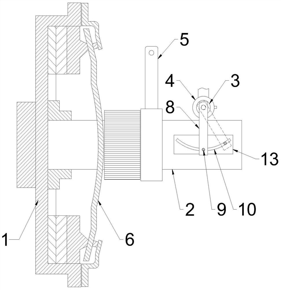
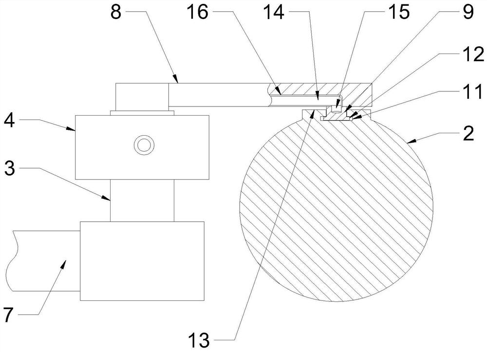
[0024] Such as figure 1 and figure 2 As shown, a push rod displacement monitoring mechanism of a vehicle clutch includes a clutch 1, a push rod 2, a rotating column 3 and an encoder 4. The push rod 2 is slidably installed on the clutch 1, and the push rod 2 is connected to the separation rocker of the clutch. The arm 5 and the push rod 2 can receive the thrust transmitted from the clutch pedal and the separation rocker arm 5 to squeeze the diaphragm spring 6 of the clutch to deform. Rotary column 3 is mounted on a bracket 7 of the vehicle chassis in a rotatable manner. The central key is connected with a connecting rod 8, and the other end of the connecting rod 8 is provided with a follower 9, and the push rod 2 is formed with an arc-shaped main limiting groove 10 that cooperates with the follower 9. The columns 3 have a common center, and the follower 9 is inserted into the main limiting groove 10. When the push rod 2 is translated, the follower 9 of the connecting rod 8 m...

Embodiment 2

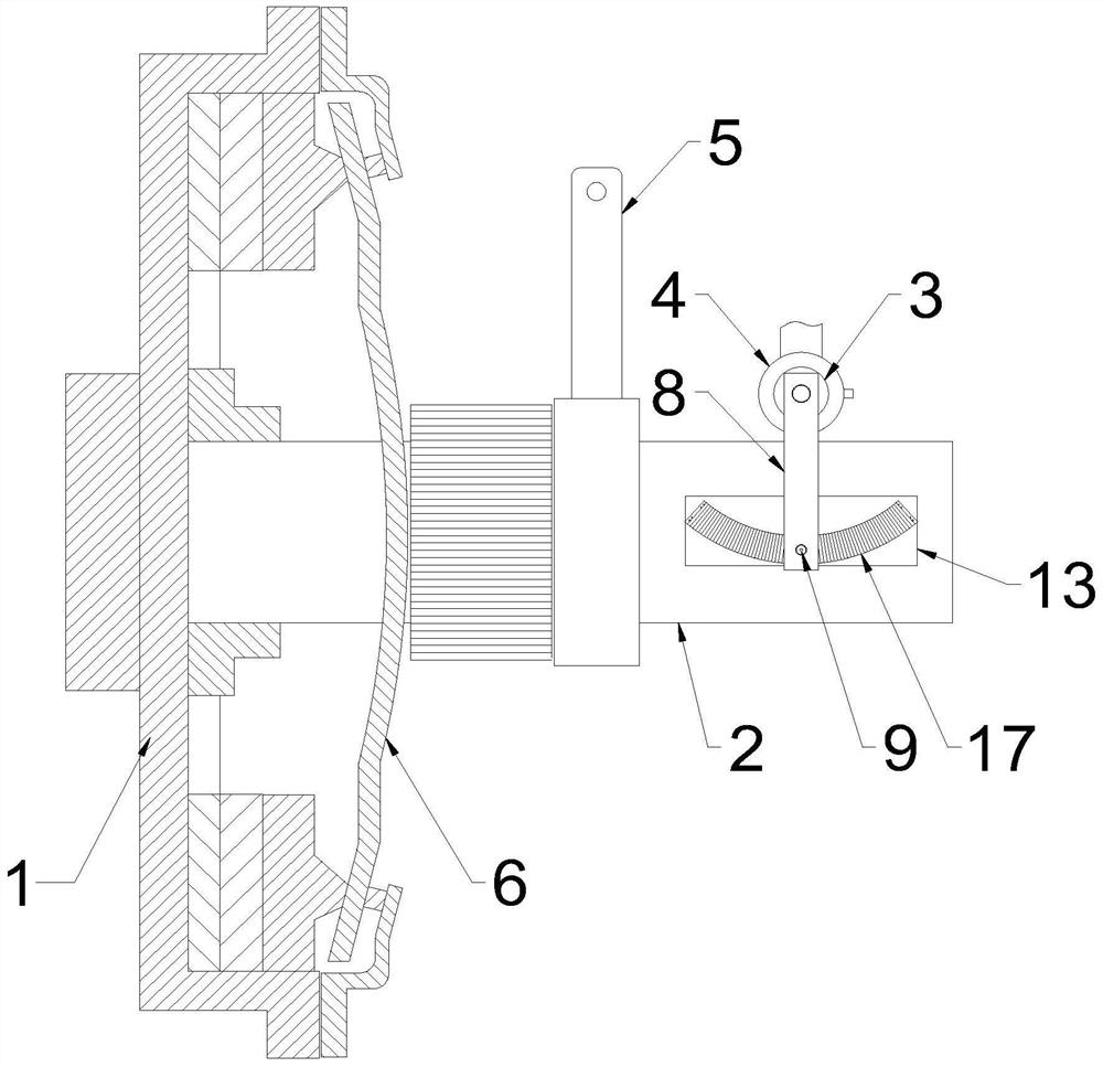
[0030] The difference between this embodiment and embodiment 1 lies in the difference of the dust-proof structure, such as image 3 As shown, the monitoring mechanism nails or glues an accordion-shaped dust cover 17 on the convex surface 13 of the connecting rod. The material of the dust cover 17 is a flexible waterproof fabric, and the dust cover 17 can cover the main limiting groove 10. Wherein, two dustproof covers 17 are installed symmetrically on the convex surface 13, and one end of the dustproof cover 17 is fixed at the arc-shaped end of the main limiting groove 10, and the other end is fixed on the connecting rod 8, when the connecting rod 8 rotates The dust cover 17 can be alternately stretched or folded, for example: when the connecting rod 8 folds the left dust cover, the right side dust cover is automatically stretched by the connecting rod, so that the main limiting groove 10 is always covered by the dust cover. Cover 17 covers, and isolation dust enters in the gr...


PUM


Abstract

The invention provides a push rod displacement monitoring mechanism of a vehicle clutch. The push rod displacement monitoring mechanism comprises a clutch and a push rod, wherein the push rod is slidably mounted on a shell of the clutch, and the push rod receives thrust transmitted by a clutch pedal to extrude a diaphragm spring of the clutch to deform. The push rod displacement monitoring mechanism is characterized by further comprising a rotating column and an encoder, wherein the rotating column is rotatably mounted on a bracket of a chassis, the rotating column is located on the side edgeof the push rod, the encoder for detecting the rotating angle of the rotating column is mounted on the rotating column, a connecting rod is mounted in the center of the top end of the rotating column,a follower is arranged at the other end of the connecting rod, an arc-shaped main limiting groove matched with the follower is formed in the push rod, the main limiting groove and the rotating columnare concentric, the follower is inserted into the main limiting groove, and when the push rod is translated, the follower of the connecting rod moves in an arc-shaped trajectory along the main limiting groove to drive the rotating column to rotate. The push rod displacement monitoring mechanism can solve the problems that an existing push rod displacement monitoring mechanism is not compact enough in structure and the detection precision needs to be improved.

Description

technical field [0001] The invention belongs to the technical field of clutches, and in particular relates to a push rod displacement monitoring mechanism of a vehicle clutch. Background technique [0002] The clutch is a common component in the mechanical transmission of an automobile. It is located in the flywheel housing between the engine and the gearbox. The driver can depress or release the clutch pedal to separate or engage the engine and the gearbox. The basic requirements for vehicle clutches are: stable and reliable power transmission performance, smooth engagement, rapid and thorough separation; convenient adjustment and repair; small size, compact structure; good wear resistance and sufficient heat dissipation capacity; convenient operation and labor saving, etc. [0003] Among them, the power transmission performance of the clutch is a key requirement for the quality of the clutch. The power transmission status of the clutch during the separation and engagement ...

Claims


Application Information

Patent Timeline
Patent Type & Authority Applications(China)
IPC IPC(8): G01M13/022
CPCG01M13/022
Inventor 温良深李留东
Owner 长春一东离合器股份有限公司苏州研发中心
Learn More