A gas chromatography device

A gas chromatographic device and gas technology, which is applied in measurement devices, instruments, scientific instruments, etc., can solve problems such as reducing the tightness of the connection between the gas column and the injection port, the sealing gasket affecting the sealing performance and life, and the vibration of the gas column. Increase the range of use, improve the sealing effect, and increase the effect of the sealing path

Active Publication Date: 2022-08-02
浙江安联检测技术服务有限公司
View PDF12 Cites 0 Cited by
  • Summary
  • Abstract
  • Description
  • Claims
  • Application Information

AI Technical Summary

Problems solved by technology

[0003] In the related technology, a gas chromatographic device is usually composed of six parts: a gas circuit system, a control system, a sampling system, a column system, a detection system and a data processing system. The nut cooperates with the threaded connection method of the sealing gasket to fully contact the aqueous solution with ethanol gas, so that the aqueous solution carries part of the ethanol. During detection, it is necessary to heat the inside of the gas chromatography device to vaporize the aqueous solution sample containing ethanol, and use the inert gas as the carrier gas for detection. , and the slight deformation of the gasket under long-term heating will affect the sealing performance and life. The end of the gas phase column needs to be cut regularly when it is heated for a long time
[0004] In view of the above-mentioned related technologies, the inventor believes that there is a moment when the carrier gas is fed into the gas phase column during the gas detection process, the impact on the gas phase column will cause the gas phase column to vibrate, and the external vibration will cause the vibration of the gas phase column, which will eventually lead to a decrease in the gas phase column. The leaky connection between the column and the injection port

Method used


Image

  • A gas chromatography device
  • A gas chromatography device
  • A gas chromatography device

Examples


Embodiment Construction

[0036] Attached to the following Figure 1-4 This application will be described in further detail.

[0037] The embodiment of the present application discloses a gas chromatography device.

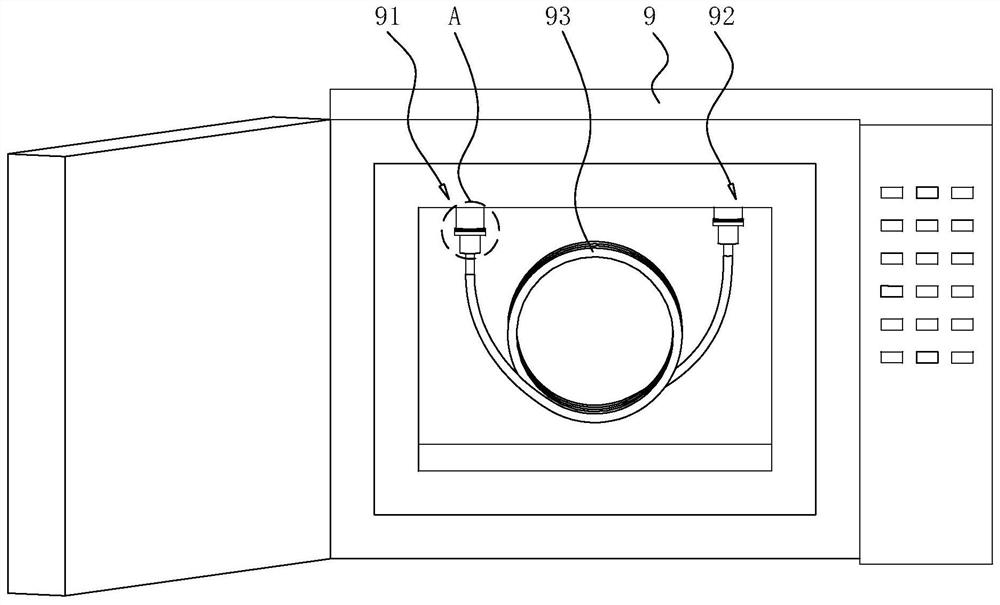
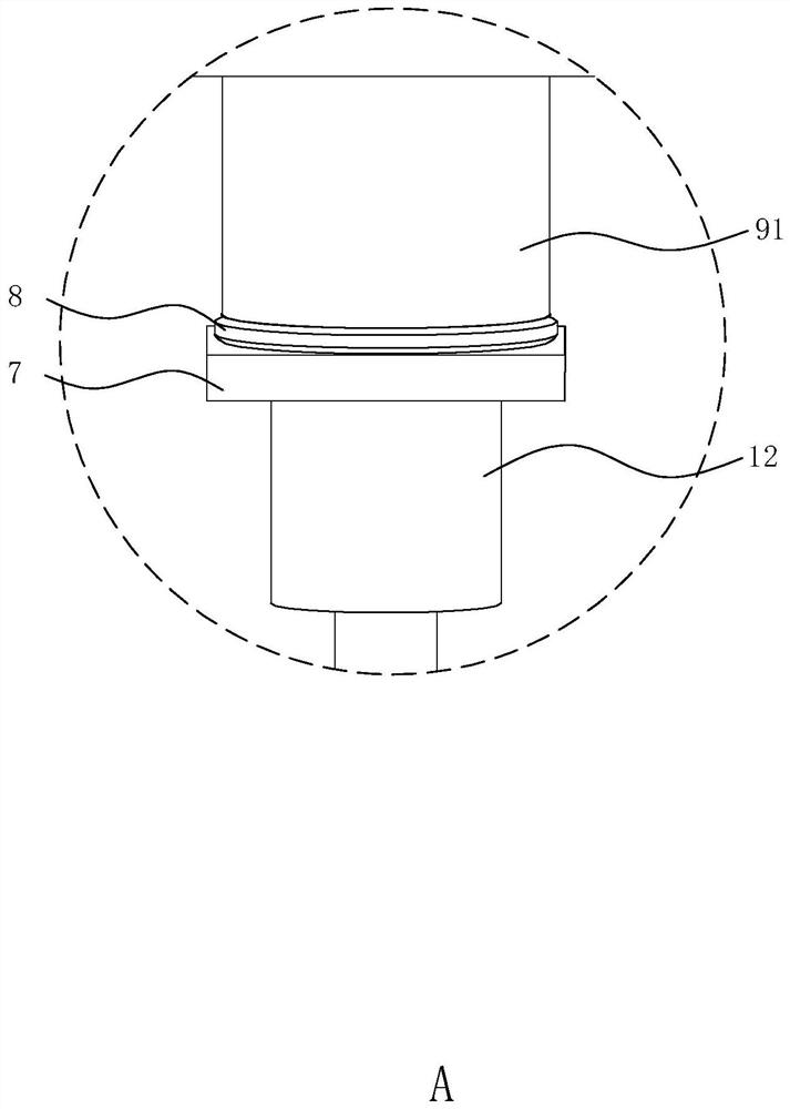
[0038] refer to figure 1 A gas chromatography device comprises a gas chromatography device body 9, the top of the inner wall of the gas chromatography device body 9 is fixedly connected with a sample inlet 91 and a sample outlet 92, and a gas column 93 is placed inside the gas chromatography device body 9, and the gas column 93 is hollow Glass tube-shaped, one end of the gas phase column 93 is communicated with the sample inlet 91, and the other end is communicated with the sample outlet 92, and a fixed tube 1 is provided between the end of the gas phase column 93 and the sample inlet 91 and the sample outlet 92, and the gas phase column 93 For the monitoring of ethanol gas.

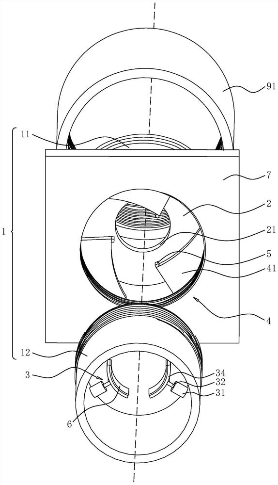
[0039] refer to figure 2 and image 3 , the fixed tube 1 is provided with a fixed component 3 and a limit co...


PUM


Abstract

The present application relates to a gas chromatography device, which comprises a fixed pipe for threaded connection between a gas column and an injection port, the fixed pipe includes an upper pipe and a lower pipe, the upper pipe and the lower pipe are connected by the same centerline thread, and a fixed pipe is arranged in the upper pipe for fixing The rubber inner ring sealed by the tube, the gas phase column runs through the rubber inner ring, the lower tube is provided with fixed components, and there are no less than two fixed components. The fixed components include an outer cylinder, an inner rod, a spring and a push plate. The inner wall of the tube is fixedly connected, and the other end is cantilevered near the centerline of the lower tube. One end of the inner rod is inserted into the outer cylinder, and the other end is fixedly connected with the push plate. The spring is located inside the inner cylinder, and one end of the spring and the inner rod are located inside the outer cylinder. One end is fixedly connected, the other end is fixedly connected with the inner wall of the outer cylinder, and the fixing tube is provided with a limiting component for the fixing component to approach or move away from the centerline of the downward tube. The present application has the effect of improving the sealing performance of the connection between the gas phase column and the injection port.

Description

technical field [0001] The present application relates to the field of gas detection devices, and in particular, to a gas chromatography device. Background technique [0002] At present, the gas chromatograph mainly uses the boiling point, polarity and different adsorption properties of different substances in the sample to realize the separation of the mixture, wherein the two phases are the stationary phase and the mobile phase; when the separated substances pass through in turn After the detector, a chromatogram composed of peak time and peak area is obtained. According to different peak times, qualitative analysis of unused substances can be performed, and quantitative detection of substances can be realized by using peak height or peak area. [0003] In the related art, a gas chromatography device usually consists of six parts: a gas circuit system, a control system, a sample injection system, a column system, a detection system and a data processing system, and the con...

Claims


Application Information

Patent Timeline
Patent Type & Authority Patents(China)
IPC IPC(8): G01N30/02G01N30/60
CPCG01N30/02G01N30/6052G01N30/606G01N30/6047
Inventor 王勇张林英张秀琳孙春花
Owner 浙江安联检测技术服务有限公司
Why Eureka
Try Eureka