Laser radar and detection method of laser radar

A laser radar and laser beam technology, applied in the field of laser detection, can solve the problems of low image definition and low point cloud density

Pending Publication Date: 2020-12-29
HUAWEI TECH CO LTD
View PDF2 Cites 17 Cited by
  • Summary
  • Abstract
  • Description
  • Claims
  • Application Information

AI Technical Summary

Problems solved by technology

In order to achieve centimeter-level distance resolution, a frequency modulation bandwidth of more than 10 GHz is required. For vehicle-mounted FMCW lidar, frequency modulation to a bandwidth of more than 10 GHz requires a frequency modulation time much longer than that of microseconds (generally on a sub-millisecond time scale). In this way, the scanning ranging time for a target point generally needs 10 -4 Seconds, that is, only about 10,000 points can be scanned in one second. If the frame rate is considered to be 24 frames per second, then there are only about 400 points in each frame, so the point cloud density is also low, and the image definition is also low.

Method used


Image

  • Laser radar and detection method of laser radar
  • Laser radar and detection method of laser radar
  • Laser radar and detection method of laser radar

Examples


Embodiment Construction

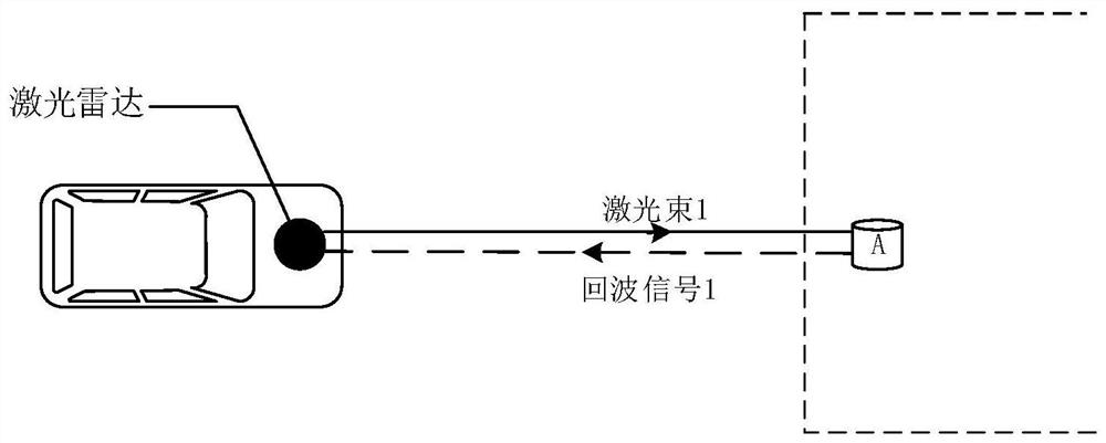
[0054] Lidar usually works by emitting high-frequency electromagnetic waves and receiving electromagnetic energy scattered by the target. By comparing and analyzing the received echo signal and detection signal, information related to the target can be extracted, such as the position information of the target. figure 1 It is a detection schematic diagram of a laser radar provided in this application. LiDAR consists of lasers and detectors. The laser emits a laser beam in a certain direction. If there is a target within a certain distance along the emitting direction of the laser beam, the laser beam can be reflected on the surface of the target. figure 1 Take the target A in the emission direction of the laser beam 1 as an example. After the laser beam 1 emitted by the laser reaches the target A, it is reflected on the surface of the target A, and the reflected signal returns to the laser radar detector as an echo signal. According to the echo signal and the local signal, the...


PUM


Abstract

The invention provides a laser radar and a detection method of the laser radar. The laser radar can be applied to the fields of automatic driving, networked vehicles and the like. The laser radar comprises a laser device, a first beam splitting module, an included angle adjusting module, a scanning module and a detection module, wherein the laser device is used for emitting N laser beams and transmitting the N laser beams to N first beam splitting modules; the first beam splitting module is used for splitting the received laser beams into first laser beams and second laser beams; the includedangle adjusting module is used for receiving the N second laser beams and adjusting an included angle between any two adjacent second echo signals in the N second laser beams to be greater than 0 degree and not greater than angular resolution; the scanning module is used for receiving the N second laser beams and emitting the N second laser beams at different detection angles; and the detection module is used for receiving the first laser beams and the corresponding echo signals, performing frequency mixing processing to obtain beat frequency signals and determining associated information of atarget object according to the beat frequency signals. Therefore, more associated information can be obtained, so that the point cloud density of a formed image can be improved, and the definition ofthe image is improved.

Description

technical field [0001] The present application relates to the technical field of laser detection, in particular to a laser radar and a laser radar detection method. Background technique [0002] LiDAR (light detection and ranging, LiDAR) is a radar system that emits laser beams to detect characteristic quantities such as the position and speed of targets. The working principle of lidar is to transmit a detection signal (laser beam) to a target object (such as a vehicle, aircraft or missile), and then compare and process the received signal (echo signal) reflected from the target object with the transmitted signal , the relevant information of the target object can be obtained, such as the target distance, azimuth, height, speed, attitude, and even shape parameters, so that the target object can be detected, tracked and identified. [0003] At present, commonly used vehicle-mounted lidars include pulse-based time-of-flight (TOF) ranging lidars and frequency modulated continu...

Claims


Application Information

Patent Timeline
Patent Type & Authority Applications(China)
IPC IPC(8): G01S17/88G01S17/08G01S7/481G01S7/487G01S7/493
CPCG01S17/88G01S17/08G01S7/481G01S7/487G01S7/493G01S7/4814G01S7/4817G01S17/42G01S17/89G01S17/34G01S7/4911G01S7/4914G01S7/4917
Inventor 王振伟曾理
Owner HUAWEI TECH CO LTD
Why Eureka
Try Eureka