
Electromagnetic element and manufacturing method thereof

A technology of electromagnetic components and manufacturing methods, which is applied in the manufacture of magnetic cores, electrical components, inductors/transformers/magnets, etc., can solve problems such as magnetic saturation, and achieve the effect of increasing stability and avoiding magnetic saturation

Pending Publication Date: 2020-12-29
SHENNAN CIRCUITS
View PDF0 Cites 0 Cited by
  • Summary
  • Abstract
  • Description
  • Claims
  • Application Information

AI Technical Summary

Problems solved by technology

[0004] The present application provides an electromagnetic component and its manufacturing method to solve the problem that the magnetic saturation phenomenon occurs due to the current in the coil of the buried magnetic electromagnetic device in the prior art that is easily affected by the current in the coil

Method used


Image

  • Electromagnetic element and manufacturing method thereof
  • Electromagnetic element and manufacturing method thereof
  • Electromagnetic element and manufacturing method thereof

Examples


Embodiment Construction

[0041] The following will clearly and completely describe the technical solutions in the embodiments of the application with reference to the drawings in the embodiments of the application. Apparently, the described embodiments are only some of the embodiments of the application, not all of them. Based on the embodiments in this application, all other embodiments obtained by persons of ordinary skill in the art without making creative efforts belong to the scope of protection of this application.

[0042] It should be noted that if there are directional indications (such as up, down, left, right, front, back...) in the embodiment of the present application, the directional indications are only used to explain the position in a certain posture (as shown in the accompanying drawings). If the specific posture changes, the directional indication will also change accordingly.

[0043] In addition, if there are descriptions involving "first", "second", etc. in the embodiments of the...


PUM

PropertyMeasurementUnit
widthaaaaaaaaaa

Abstract

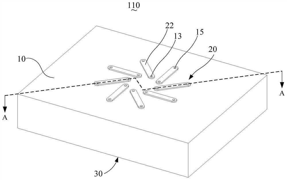
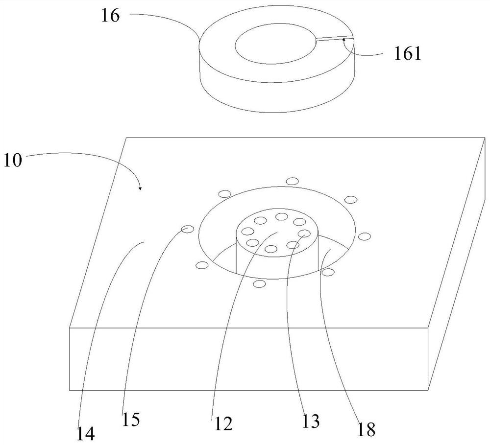
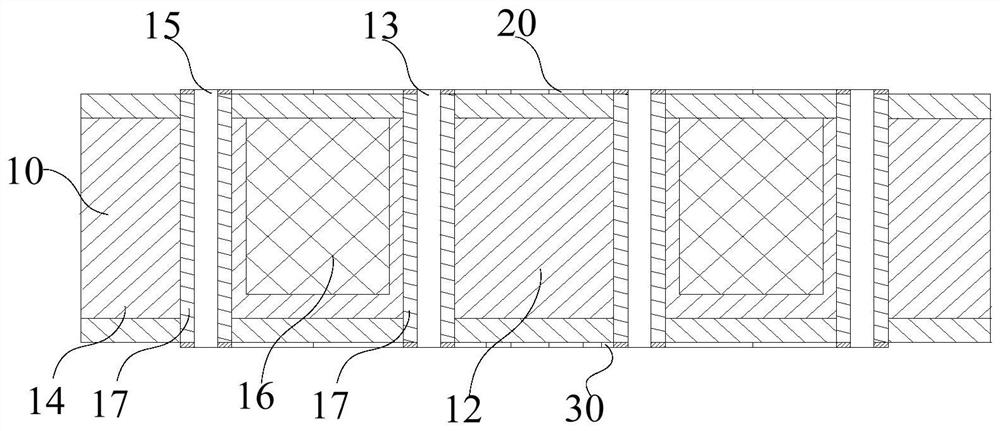
The invention discloses an electromagnetic element and a manufacturing method thereof. The electromagnetic element comprises a substrate, a magnetic core, a transmission line layer and a plurality ofconductive parts, wherein the substrate comprises a central part and a peripheral part, a plurality of internal through holes penetrating through the substrate are formed in the central part, a plurality of external through holes penetrating through the substrate are formed in the peripheral part, and an annular accommodating groove is formed between the central part and the peripheral part to accommodate the magnetic core; the transmission line layer is arranged at two opposite sides of the substrate and comprises a plurality of wire patterns which are arranged at intervals along the circumferential direction of the annular accommodating groove, and each wire pattern is bridged between one corresponding internal via hole and one corresponding external via hole; the plurality of conductiveparts are arranged in the internal via hole and the external via hole and are used for sequentially connecting the wire patterns on the two transmission line layers so as to form a coil loop for transmitting current around the magnetic core; an air gap is formed in the magnetic core. The electromagnetic element is advantaged in that the air gap is formed in the magnetic core, so stability of theinfluence of the magnetic core on the current can be improved.

Description

technical field [0001] The present application relates to the technical field of electromagnetic element manufacturing, in particular to an electromagnetic element and a manufacturing method thereof. Background technique [0002] The existing embedded magnetic electromagnetic device usually embeds the magnetic core in a substrate, and then arranges conductive metal layers on both sides of the substrate, and electrically connects the conductive metal layers on both sides by punching holes, thereby forming a surrounding magnetic field. Core set turns. [0003] However, the existing buried magnetic electromagnetic device is easily affected by the current in the coil during operation, resulting in magnetic saturation. Contents of the invention [0004] The present application provides an electromagnetic element and a manufacturing method thereof, so as to solve the problem in the prior art that the embedded magnetic electromagnetic device is easily affected by the current in ...

Claims


Application Information

Patent Timeline
Patent Type & Authority Applications(China)
IPC IPC(8): H01F27/24H01F27/26H01F27/28H01F41/00H01F41/02H01F41/04
CPCH01F27/24H01F27/266H01F27/28H01F41/00H01F41/0206H01F41/04
Inventor 郭伟静
Owner SHENNAN CIRCUITS
Learn More