Mutual-inductance type current-limiting reactor

A technology of current-limiting reactors and transformers, which is applied to emergency protection circuit devices, electrical components, circuit devices and other directions for limiting overcurrent/overvoltage, can solve the problems of complicated working process of current-limiting reactors, and achieve structural Simple, easy to operate, wide range of effects

Inactive Publication Date: 2019-06-07
HUAZHONG UNIV OF SCI & TECH
View PDF3 Cites 0 Cited by
  • Summary
  • Abstract
  • Description
  • Claims
  • Application Information

AI Technical Summary

Problems solved by technology

[0008] The invention provides a mutual inductance type current-limiting reactor, which is used to solve the problem of complicated working process existing in the existing current-limiting reactor

Method used


Image

  • Mutual-inductance type current-limiting reactor
  • Mutual-inductance type current-limiting reactor
  • Mutual-inductance type current-limiting reactor

Examples


Embodiment 1

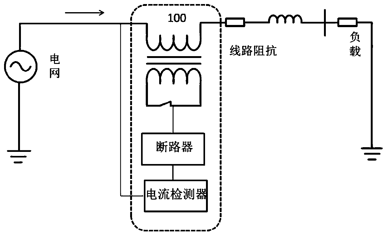
[0028] A mutual inductance type current limiting reactor 100 includes: a mutual inductor, a circuit breaker, and a current detector. Among them, one end of the primary side of the transformer is used for the output end of the external power grid, and the other end is used for the external load, the secondary side of the transformer is connected to the output end of the circuit breaker, and the input end of the circuit breaker is connected to the output end of the current detector. , the input terminal of the current detector is used for the output terminal of the external grid; the current detector is used to collect the output current of the grid in real time, and judge whether the output current is less than the preset current threshold, if so, control the circuit breaker to be in the closed state, so that the secondary The side is in a short circuit state, if not, the control circuit breaker is turned off so that the secondary side is in an open state.

[0029] It should be...


PUM


Abstract

The invention relates to a mutual-inductance type current-limiting reactor, and the reactor comprises a mutual inductor, a circuit breaker and a current detector. One end of the primary side of the mutual inductor is externally connected with the output end of a power grid, and the other end of the primary side of the mutual inductor is externally connected with a load. The secondary side of the mutual inductor is connected with the circuit breaker, and the circuit breaker is further connected with the current detector. The current detector is externally connected with the output end of the power grid. The current detector is used for collecting an output current of the power grid in real time and judging whether the output current is smaller than a preset current threshold value or not: if yes, controlling the circuit breaker to be turned on, and supplying power to the secondary side; if not, controlling the circuit breaker to be turned off. The current detector is adopted to realizeautomatic control of the current of the power grid, the problem that the turn ratio of the primary side and the secondary side is limited due to existing shunt control is solved. Moreover, the magnitude of the current input to the secondary side does not need to be adjusted, and only the circuit breaker needs to be controlled to be turned on and off, so the operation is convenient. In addition, the current-limiting reactor provided by the invention is simple in structure and low in cost.

Description

technical field [0001] The invention relates to the technical field of adjustable reactors, in particular to a mutual inductance current-limiting reactor. Background technique [0002] With the increasing scale of the power grid, various distributed energy sources are connected to the power grid, and the degree of grid interconnection is greatly increased. The fault current limiting level of the power grid is close to the upper limit of the interrupting capacity of the existing circuit breaker. Therefore, in order to effectively limit the size of the short-circuit current, To improve the short-circuit capacity, power system fault current limiter (FCL) came into being. The active action current limiter represented by FCL presents a small reactance characteristic during the normal operation of the power grid; when the power grid fails, it immediately changes to a large impedance, limiting the fault current to a lower level, and realizing fault limitation. Dynamic control of f...

Claims


Application Information

Patent Timeline
Patent Type & Authority Applications(China)
IPC IPC(8): H02H9/02
Inventor 李达义侯宇凝王庭康陈建春王海飞
Owner HUAZHONG UNIV OF SCI & TECH
Why Eureka
Try Eureka