Heat regeneration system of combined heat and power cogeneration unit

A cogeneration unit and heat recovery system technology, applied in the direction of electric components, mechanical equipment, electromechanical devices, etc., can solve the problems of large volume, no peripheral heat production recovery system, complex structure, etc., and achieve the realization of cogeneration Effect

Active Publication Date: 2020-12-29
JIANGSU LEE & MAN PAPER MFG
View PDF7 Cites 0 Cited by
  • Summary
  • Abstract
  • Description
  • Claims
  • Application Information

AI Technical Summary

Problems solved by technology

[0004] The purpose of the present invention is to solve the disadvantages that the existing cogeneration units are generally large in size and complex in structure, and for microcomputers, there is generally no peripheral heat production and recovery system, which can only meet the needs of small-scale power generation, and the proposed A heat recovery system for combined heat and power units

Method used


Image

  • Heat regeneration system of combined heat and power cogeneration unit
  • Heat regeneration system of combined heat and power cogeneration unit
  • Heat regeneration system of combined heat and power cogeneration unit

Examples


Embodiment 1

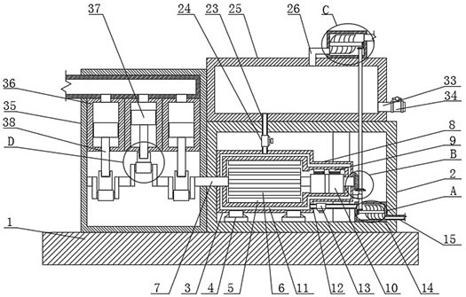
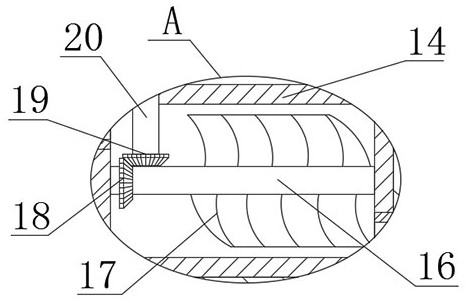
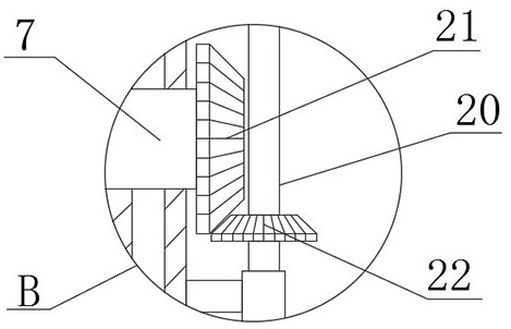
[0026] refer to Figure 1-5 , a heat recovery system for a combined heat and power unit, comprising a bottom plate 1, the top of the bottom plate 1 is fixedly connected to an organic case 2, a microcomputer 3 is fixedly connected to one side of the inner wall of the case 2, and the bottom of the microcomputer 3 is fixedly connected to a support foot 4 , the legs 4 are fixedly connected to the inner wall of the bottom of the cabinet 2, the inner wall of the microcomputer 3 is fixedly provided with a stator 5, the stator 5 is rotated and provided with a rotor 6, the rotor 6 is fixedly sleeved with a first rotating shaft 7, and the microcomputer 3 An insulating cover 8 is fixedly connected to one side of the insulating cover 8, and a brush 9 is fixedly connected to the inner wall of the top of the insulating cover 8. One end of the first rotating shaft 7 extends to the outside of the insulating cover 8, and the first rotating shaft 7 in the insulating cover 8 is fixedly sleeved. ...

Embodiment 2

[0036] refer to Figure 1-5, a heat recovery system for a combined heat and power unit, comprising a bottom plate 1, the top of the bottom plate 1 is fixedly welded with an organic case 2, one side of the inner wall of the case 2 is fixedly connected with a microcomputer 3 by screws, and the bottom of the microcomputer 3 is fixedly welded with a support The feet 4 and the supporting feet 4 are fixedly connected on the inner wall of the bottom of the chassis 2 by screws, the inner wall of the microcomputer 3 is fixedly provided with a stator 5, and a rotor 6 is provided for rotating in the stator 5, and a first rotating shaft 7 is fixedly sleeved on the rotor 6 One side of the microcomputer 3 is fixedly welded with an insulating cover 8, and the top inner wall of the insulating cover 8 is fixedly welded with a brush 9, and one end of the first rotating shaft 7 extends outside the insulating cover 8, and the first rotating shaft in the insulating cover 8 7. The upper fixed sleev...


PUM


Abstract

The invention belongs to the technical field of combined heat and power cogeneration units, particularly relates to a heat regeneration system of combined heat and power cogeneration unit, and aims tosolve the problems that an existing heat and power cogeneration unit is generally large in size and complex in structure, and for a microcomputer, an external heat production recovery system does notexist generally, and only the small electricity production requirement can be met. The following scheme is proposed, the heat regeneration system comprises a bottom plate; the top of the bottom plateis fixedly connected with a case, the inner wall of one side of the case is fixedly connected with a microcomputer, the bottom of the microcomputer is fixedly connected with supporting feet, the supporting feet are fixedly connected to the inner wall of the bottom of the case, a stator is fixedly arranged on the inner wall of the microcomputer, and a rotor is rotatably arranged in the stator. A cooling chamber is arranged on the microcomputer and an insulating cover, cold water can be injected to cool the microcomputer, normal work of the microcomputer is maintained, meanwhile, warm water inthe cooling cavity can be discharged through a first guide pipe and conveyed out through a first water pump, and heat and power cogeneration of the microcomputer is achieved.

Description

technical field [0001] The invention relates to the technical field of cogeneration units, in particular to a heat recovery system for cogeneration units. Background technique [0002] Combined heat and power, also known as combined heat and power. Combined heat and power can greatly improve the thermal efficiency of thermal power plants. Because, in general condensing units, the exhaust steam loss of the steam turbine is very large. The heat recovery system of the combined heat and power unit, through some methods, passes part or all of the steam through the steam turbine to do work, and then outputs it to the heat user to reduce the loss of exhaust steam. Moreover, cogeneration solves the problem of central heating in cities and replaces the small boilers everywhere. The existing heat recovery system of cogeneration units generally includes: body, power generation system and heat exchange system, power generation system and heat exchange system They are all arranged in ...

Claims


Application Information

Patent Timeline
Patent Type & Authority Applications(China)
IPC IPC(8): H02K9/19H02K7/18H02K7/116F04D13/06F04D13/02F01B23/10
CPCH02K9/19H02K7/1807H02K7/1163F04D13/06F04D13/02F01B23/10Y02E20/14
Inventor 李文斌
Owner JIANGSU LEE & MAN PAPER MFG
Why Eureka
Try Eureka