
Control signal synchronization method, device and system, vehicle and storage medium

A technology for controlling signals and vehicles, which is applied in the fields of control signal synchronization, vehicles and storage media, and can solve problems such as phase deviation, internal clock characteristic deviation, torque fluctuation, etc.

Pending Publication Date: 2020-12-29
CHINA FIRST AUTOMOBILE
View PDF0 Cites 1 Cited by
  • Summary
  • Abstract
  • Description
  • Claims
  • Application Information

AI Technical Summary

Problems solved by technology

If there is a deviation in the PWM synchronous phase, there will be a certain torque fluctuation, which will cause different degrees of vibration in the vehicle and seriously affect the driving comfort.
[0004] In the prior art, the internal clock and the external clock are used to synchronize the PWM signal, but the clock system can guarantee the phase synchronization at the current moment, and at the moment of the next pulse cycle, the internal clock will have a characteristic deviation with the increase of the use time, so that the internal The phase of the clock signal deviates from the phase of the external clock signal, which will still cause vibration and torque fluctuations

Method used


Image

  • Control signal synchronization method, device and system, vehicle and storage medium
  • Control signal synchronization method, device and system, vehicle and storage medium
  • Control signal synchronization method, device and system, vehicle and storage medium

Examples


Embodiment 1

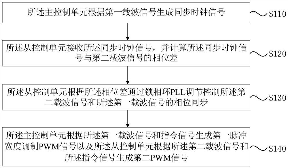
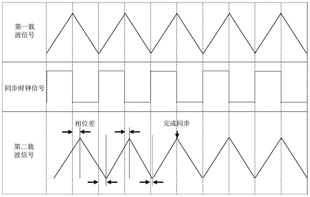
[0032] Figure 1A It is a flow chart of a method for synchronizing control signals provided by Embodiment 1 of the present invention. This embodiment can be applied to control PWM when the motor system in a vehicle (especially an electric vehicle) is driven by more than one drive unit Signals are synchronized. The method for controlling signal synchronization provided in this embodiment can be executed by the device for controlling signal synchronization provided in this embodiment of the present invention. The device can be implemented in software and / or hardware, and integrated into a system for executing this method.

[0033] It should be noted that in the embodiment of the present invention, two drive units, the first drive unit and the second drive unit, and two control units, the master control unit and the slave control unit, are taken as examples to illustrate the method of synchronizing control signals , in the actual application process, the number of control units a...

Embodiment 2

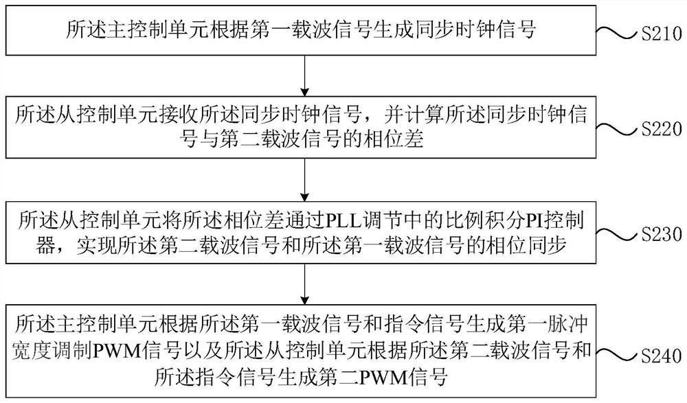
[0056] Figure 2A It is a flowchart of a method for controlling signal synchronization provided by Embodiment 2 of the present invention. The embodiments of the present invention are optimized on the basis of the foregoing embodiments. Optionally, this embodiment explains in detail the process of controlling phase synchronization between the second carrier signal and the first carrier signal.

[0057] see Figure 2A , the method of this embodiment includes but not limited to the following steps:

[0058] S210, the main control unit generates a synchronous clock signal according to the first carrier signal.

[0059] S220. The slave control unit receives the synchronous clock signal, and calculates a phase difference between the synchronous clock signal and the second carrier signal.

[0060] S230. The slave control unit uses the phase difference through a proportional-integral PI controller in PLL adjustment to implement phase synchronization between the second carrier sign...

Embodiment 3

[0073] image 3 A schematic structural diagram of a device for controlling signal synchronization provided by Embodiment 3 of the present invention, as shown in image 3 As shown, the device may include:

[0074] The clock signal generation module 310 and the first signal generation module 340 configured in the master control unit, the phase difference determination module 320, the phase synchronization control module 330 and the second signal generation module 350 configured in the slave control unit;

[0075] The clock signal generating module 310 is configured to generate a synchronous clock signal according to a first carrier signal, wherein the first carrier signal is generated by the main control unit;

[0076] The phase difference determination module 320 is configured to receive the synchronous clock signal, and calculate the phase difference between the synchronous clock signal and a second carrier signal, wherein the second carrier signal is generated by the slave c...


PUM


Abstract

The embodiment of the invention discloses a control signal synchronization method, device and system, a vehicle and a storage medium. The method comprises: the main control unit generating a synchronous clock signal according to a first carrier signal; the slave control unit receiving the synchronous clock signal and calculating the phase difference between the synchronous clock signal and a second carrier signal; the slave control unit adjusting and controlling phase synchronization of the second carrier signal and the first carrier signal through a phase-locked loop PLL according to the phase difference; the master control unit generating a first pulse width modulation (PWM) signal according to the first carrier signal and the command signal, and the slave control unit generating a second PWM signal according to the second carrier signal and the command signal. According to the technical scheme provided by the embodiment of the invention, synchronization of the PWM signals can be realized, so that abnormal vibration generated in a vehicle driving process is reduced.

Description

technical field [0001] The embodiments of the present invention relate to signal synchronization technology, and in particular to a method, device, system, vehicle and storage medium for controlling signal synchronization. Background technique [0002] With the shortage of energy and the deterioration of the environment, people pay more and more attention to electric vehicles. As the power source of electric vehicles, the reliability and stability of electric drive systems directly determine the safety and comfort of electric vehicles. [0003] The motor system of an electric vehicle includes a motor control unit, which controls the drive control unit and the insulated gate bipolar transistor (Insulated Gate Bipolar Transistor, IGBT) by generating a pulse width modulation (Pulse Width Modulation, PWM) control signal. The module drives the motor. If the motor system is driven by more than one set of drive control units and IGBT modules, it will involve the synchronization of ...

Claims


Application Information

Patent Timeline
Patent Type & Authority Applications(China)
IPC IPC(8): H03L7/081H03K7/08
CPCH03L7/081H03K7/08
Inventor 李帅金程师浩浩
Owner CHINA FIRST AUTOMOBILE
Learn More