Ultrasonic examination device

A technology of ultrasonic examination and ultrasonic transducer, which is applied in the directions of ultrasonic/sonic/infrasonic diagnosis, ultrasonic/sonic/infrasonic Permian technology, ultrasonic/sonic/infrasonic image/data processing, etc., which can solve the problem of difficult to achieve accurate puncture , limitations, it is difficult to ensure that the puncture path of the puncture needle is on the scanning plane, etc., to achieve the effect of improving puncture efficiency and accuracy, low trauma, simple and fast surgical treatment

Pending Publication Date: 2021-01-01
ULTRASOUND ASSISTED MEDTECH PTE LTD
View PDF0 Cites 6 Cited by
  • Summary
  • Abstract
  • Description
  • Claims
  • Application Information

AI Technical Summary

Problems solved by technology

When the ultrasonic transducer rotates in the probe end shell to realize three-dimensional imaging, the puncture frame fixed on the probe end shell cannot rotate synchronously with the ultrasonic transducer, and it is difficult to ensure that the puncture path of the puncture needle is on the scanning plane of the ultrasonic probe. On, it is difficult to achieve accurate puncture
Therefore, there are currently very few three-dimensional ultrasound probes used in ultrasound interventional therapy. Most of the ultrasound interventional therapy still uses two-dimensional ultrasound probes, but two-dimensional ultrasound probes can only provide two-dimensional ultrasound image information, which is very important for lesion diagnosis and puncture operations. Guidance is limited

Method used


Image

  • Ultrasonic examination device
  • Ultrasonic examination device
  • Ultrasonic examination device

Examples


Embodiment 1

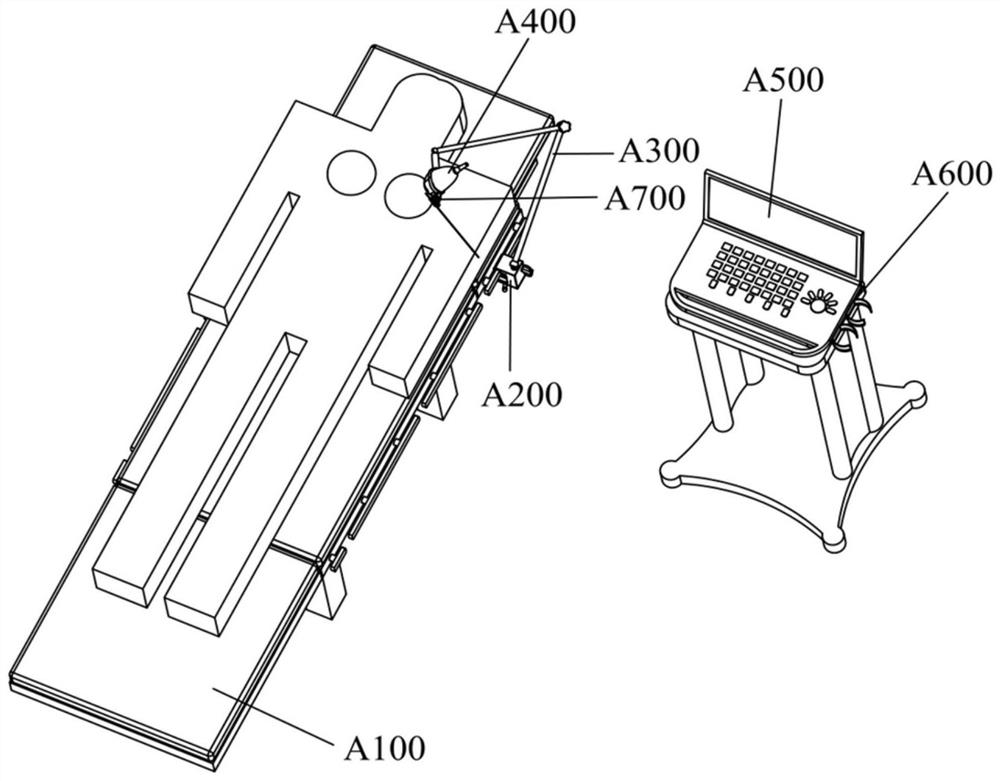
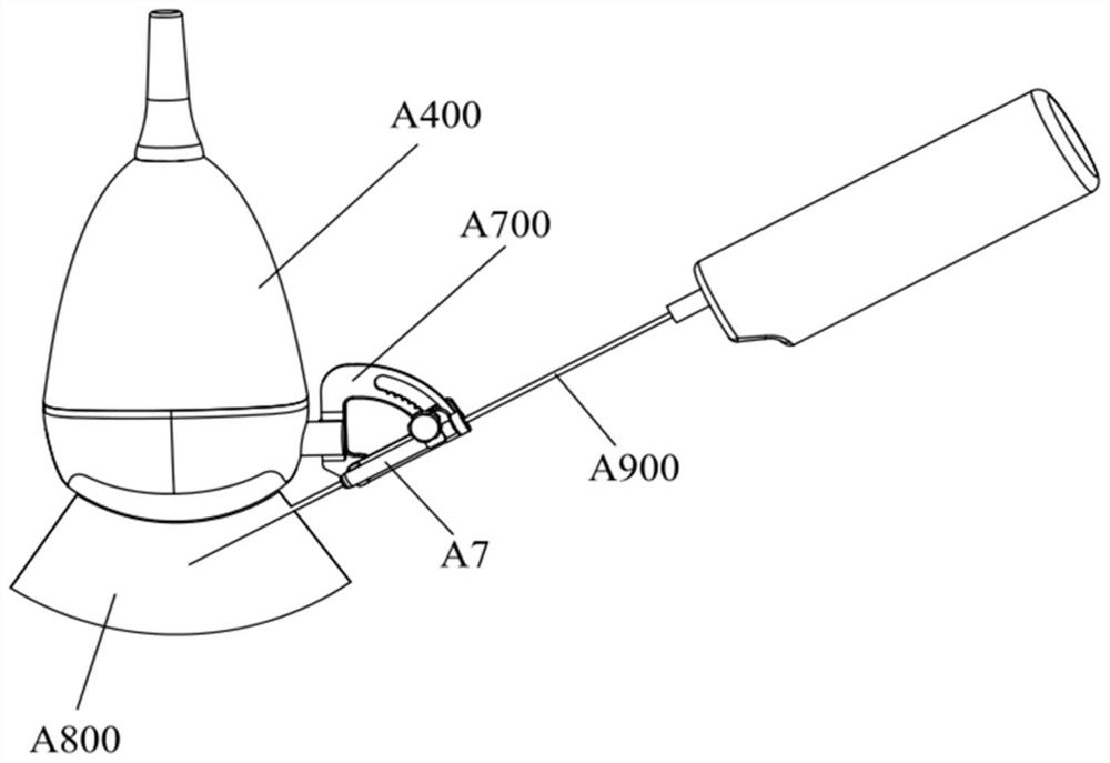
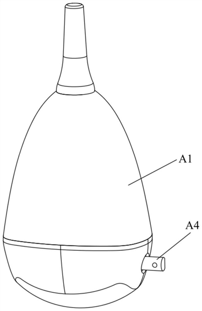
[0088]Such asFigure 1-Figure 6 As shown, this embodiment provides an ultrasonic inspection apparatus, including a 3D ultrasonic probe A400 and a puncture frame A700 installed on the ultrasonic probe A400. The ultrasonic probe A400 includes a mounting shell A1 and an ultrasonic transducer A2 arranged in the mounting shell A1. The ultrasonic transducer A2 is spaced apart from the inner wall of the mounting shell A1. The ultrasonic transducer A2 can be rotated in the mounting shell A1 to scan the relevant parts to be inspected. The puncture frame A700 is arranged outside the mounting shell A1. The puncture frame A700 is provided with a puncture guide hole A721 through which the puncture needle A900 passes. After the ultrasound transducer A2 finds the lesion, the puncture needle A900 is inserted into the lesion to obtain living tissue.

[0089]The ultrasonic inspection device also includes an operating table A100 and a driving mechanism arranged on the operating table A100. The patient lie...

Embodiment 2

[0106]The difference between this embodiment and the first embodiment is:

[0107]SeePicture 9 withPicture 10 As shown, the ultrasonic inspection apparatus of this embodiment further includes a second driving member A8 and a second transmission mechanism A9. The second driving member A8 is arranged in the mounting shell A1, and the output end of the second driving member A8 is connected to the second transmission mechanism A9. The second transmission mechanism A9 is connected with a second main shaft A10, and the second main shaft A10 extends out of the escape hole on the mounting shell A1 and is connected with the puncture frame A700. The second driving member A8 is preferably a motor.

[0108]At the same time, the outputs of the second driving part A8 and the first driving part A3 are controlled, so that the puncture frame A700 and the ultrasonic transducer A2 are controlled to rotate synchronously. When the puncture needle A900 is bent out of the image plane and the puncture needle A90...

Embodiment 3

[0113]The difference between this embodiment and the first embodiment is:

[0114]SeePicture 11 withPicture 12 As shown, in the ultrasonic inspection apparatus of this embodiment, the mounting shell A1 is elongated. The mounting shell A1 includes a probe end shell A11 and a shell A12 that are connected. The probe end shell A11 includes a head and an acoustically transparent hollow rod. The head is sealed at one end of the sound-transmitting hollow rod. The shell A12 communicates with the other end of the sound-transmitting hollow rod. The ultrasonic transducer A2 and the first spindle A4 are both arranged in the sound-transmitting hollow rod. The first driving member A3 is arranged in the housing A12. An escape hole is provided on the sound-transmitting hollow rod. The first main shaft A4 protrudes out of the sound-permeable hollow rod from the avoiding hole through the connecting piece, and is connected with the puncture frame A700. In this embodiment, the connecting piece is a connec...


PUM


Abstract

The invention relates to the technical field of medical equipment, in particular to an ultrasonic examination device. The ultrasonic examination device comprises a mounting shell, an ultrasonic transducer and a puncture frame. The ultrasonic transducer is rotatably arranged in an inner cavity of the mounting shell, and the ultrasonic transducer and the mounting shell are arranged at an interval; and the puncture frame is arranged on the outer side of the mounting shell, a puncture guide hole allowing a puncture needle to penetrate through is formed in the puncture frame, and the puncture frameand the ultrasonic transducer can rotate synchronously, so that the axis of the puncture guide hole and the real-time scanning plane of the ultrasonic transducer are coplanar. According to the ultrasonic examination device, the puncture frame and the ultrasonic transducer rotate synchronously, so that it is guaranteed that a puncture path is always located in the real-time scanning plane of the ultrasonic transducer, accurate positioning is provided for puncture operation, the puncture efficiency and accuracy are improved, the operation time is shortened, the operation difficulty is lowered,and accurate, low-trauma, simple and rapid operation treatment is achieved.

Description

[0001]This application claims the priority of the following applications: a Chinese patent application with an application number of 201922108008.0 filed on November 29, 2019, the entire content of the above patent application is incorporated herein by reference.Technical field[0002]The invention relates to the technical field of medical equipment, in particular to an ultrasonic inspection device.Background technique[0003]Ultrasound examination is the basic method for doctors to obtain disease information and the key to diagnosis of disease. The ultrasound interventional diagnosis and treatment device generally includes an ultrasound probe and a puncture frame installed on the ultrasound probe. After the ultrasound probe diagnoses the location of the lesion, a puncture needle is inserted into the lesion to obtain living tissue.[0004]Take the breast cancer biopsy puncture operation as an example. Existing diagnostic devices that generally use a two-dimensional ultrasound probe with a...

Claims


Application Information

Patent Timeline
Patent Type & Authority Applications(China)
IPC IPC(8): A61B17/34A61B8/08
CPCA61B17/3403A61B8/0841A61B2017/3413A61B2017/3405A61B8/4444A61B8/44A61B8/0825A61B8/0833A61B8/085A61B8/4218A61B8/58
Inventor 袁进强赵可娜毛佳炜刘文海周佳蒋祖平
Owner ULTRASOUND ASSISTED MEDTECH PTE LTD
Why Eureka
Try Eureka