
Square tube two-way synchronous bending machining device for mechanical equipment production and assembly

A technology of production assembly and two-way synchronization, which is applied in the field of mechanical processing, can solve the problems of consistency, the square tube is easy to get stuck between the fixed wheel and the bending wheel, and the bending length at both ends of the square tube cannot be guaranteed.

Inactive Publication Date: 2021-01-01
林召怀
View PDF1 Cites 5 Cited by
  • Summary
  • Abstract
  • Description
  • Claims
  • Application Information

AI Technical Summary

Problems solved by technology

[0005] In order to solve the above technical problems, the present invention provides a square tube bidirectional synchronous bending processing device for the production and assembly of mechanical equipment, to solve the problem that after the length of the square tube changes, it needs to be measured and adjusted again, and the bending length at both ends of the square tube cannot be guaranteed. Keep consistent, and after the bending process is completed, the square tube is easy to get stuck between the fixed wheel and the bending wheel, and it is necessary to manually tap the bent ends of the square tube to take out the square tube

Method used


Image

  • Square tube two-way synchronous bending machining device for mechanical equipment production and assembly
  • Square tube two-way synchronous bending machining device for mechanical equipment production and assembly
  • Square tube two-way synchronous bending machining device for mechanical equipment production and assembly

Examples


Embodiment

[0036] as attached figure 1 to attach Figure 10 Shown:

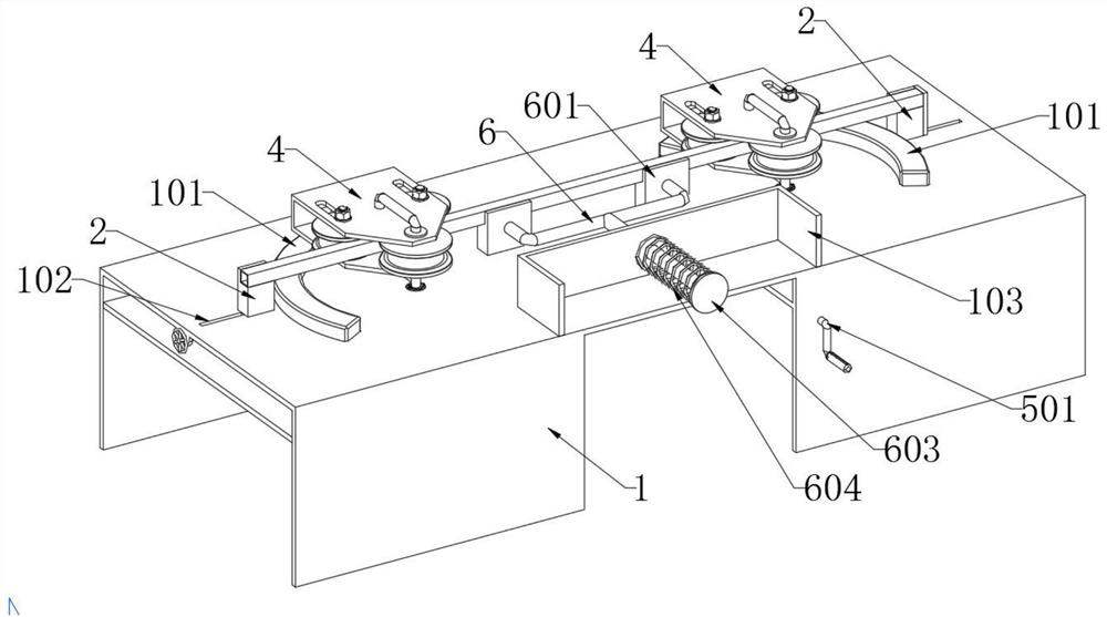
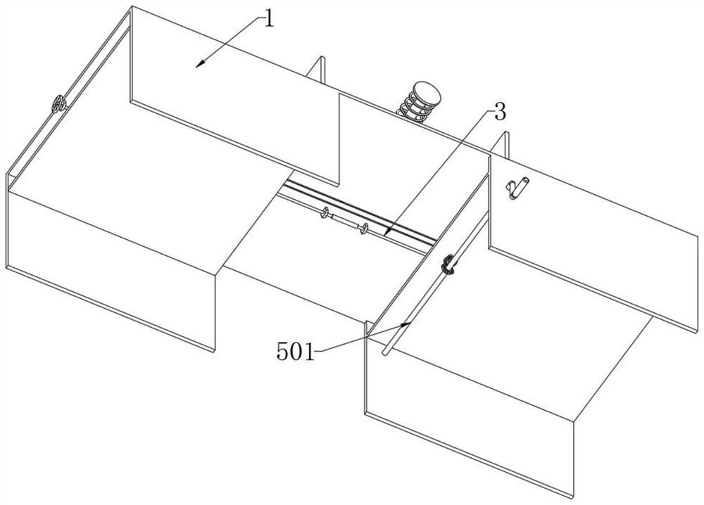
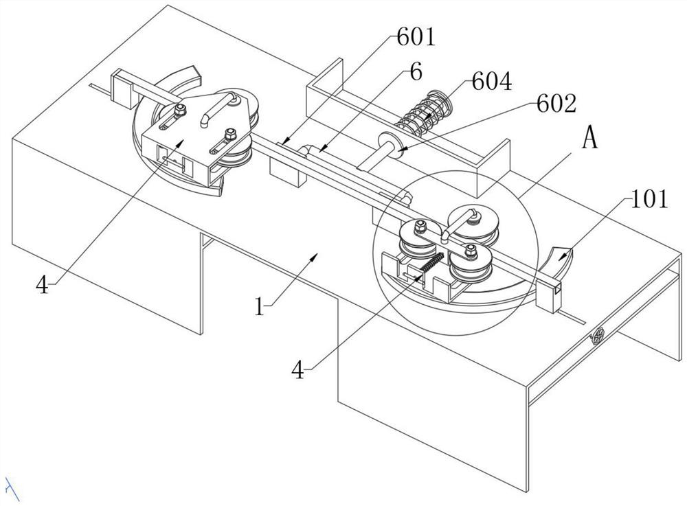
[0037] The invention provides a two-way synchronous bending processing device for square tubes used in the production and assembly of mechanical equipment, including a bending mechanism 4, a driving mechanism 5, and a discharge push rod 6; the bending mechanism 4 is provided with two groups, which are respectively rotated and installed on the processing platform 1, and the bottom side of the bending mechanism 4 are equipped with arc backing plates 101, the arc backing plates 101 are symmetrically installed on the two ends of the processing platform 1, and the outer sides of the arc backing plates 101 are respectively slidably installed There is an L-shaped support frame A2, and the L-shaped support frame A2 is slidably installed in the adjustment groove A102 through the clamp plate 201 at the bottom. The bottom of the clamp plate 201 is also connected with a threaded cylinder 2011, and the threaded cylinder 2011 is res...


PUM


Abstract

The invention provides a square tube two-way synchronous bending machining device for mechanical equipment production and assembly. The square tube two-way synchronous bending machining device comprises arc-shaped base plates; L-shaped supporting frames A are further slidably mounted at the outer sides of the arc-shaped base plates correspondingly, the L-shaped supporting frames A are slidably mounted in adjusting grooves A through clamping plates at the bottoms of the L-shaped supporting frames A, threaded cylinders are further connected to the bottoms of the clamping plates, and adjusting screw rods are inserted into the threaded cylinders in a penetrating manner and engaged with the threaded cylinders correspondingly; and a driving mechanism is installed at the inner side of a machiningplatform and is in transmission connection with tube bending linkage gears on the tube bending mechanisms, the front end of a discharging push rod is of a U-shaped structure and is connected with twosets of L-shaped supporting frames B, and the rear end of the discharging push rod is connected with an inner baffle, then penetrates through a U-shaped frame and is sleeved with a reset spring. theadjusting screw rods drive the two L-shaped supporting frames A to conduct synchronous sliding adjustment so that the bent lengths of the two ends of a square tube can be kept consistent all the time,the bent square tube can be pushed out by pushing an outer baffle and the L-shaped supporting frames B, and the square tube returns under the action of the reset spring and the inner baffle after being loosened.

Description

technical field [0001] The invention belongs to the technical field of mechanical processing, and more specifically relates to a square tube bidirectional synchronous bending processing device used in the production and assembly of mechanical equipment. Background technique [0002] Square tube refers to a thin-walled steel tube with a hollow square cross-section. This type of steel tube is also called cold-bent steel profile. This type of steel tube has excellent mechanical properties, acid and alkali corrosion resistance, and excellent weather resistance and welding processing characteristics. , so it has a wide range of applications in the fields of production, construction, petrochemical, power engineering and machinery manufacturing. The square tubes are generally standard specifications when used, so secondary processing is often required on site. The processing methods include welding, bending and cutting. Now in practical applications, bending is required. [0003] ...

Claims


Application Information

Patent Timeline
Patent Type & Authority Applications(China)
IPC IPC(8): B21D7/16B21D43/00B21D45/02
CPCB21D7/16B21D43/003B21D45/02
Inventor 林召怀
Owner 林召怀
Learn More