Straightening device for reinforcing steel bar machining

A straightening device and steel bar processing technology, which is applied in the field of steel bar straightening, and can solve the problems of rear device collision and lack of transition.

Active Publication Date: 2021-01-01
JIANGSU POWER TRANSMISSION & DISTRIBUTION CO LTD
View PDF1 Cites 3 Cited by
  • Summary
  • Abstract
  • Description
  • Claims
  • Application Information

AI Technical Summary

Problems solved by technology

The above-mentioned patents have the following deficiencies: vertical alignment first, and then horizontal alignment, but there is a lack of transition between the longi

Method used


Image

  • Straightening device for reinforcing steel bar machining
  • Straightening device for reinforcing steel bar machining
  • Straightening device for reinforcing steel bar machining

Examples


Embodiment 1

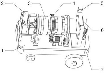
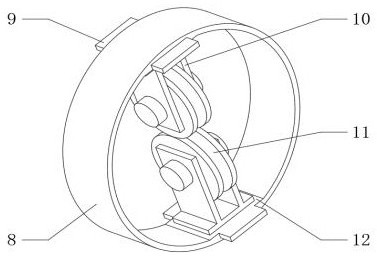
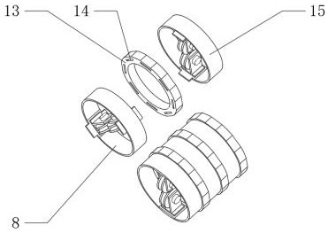
[0036] A straightening device for steel bar processing, such as Figure 1-7As shown, it includes base plate 1 and straightening assembly 3, the top outer wall of base plate 1 is fixedly connected with discharge assembly 2, the top outer wall of base plate 1 is fixedly connected with support plate 7, and the top outer wall of support plate 7 is fixedly connected with stand 5, stand 5 The outer wall of one side is fixedly connected with the feeding assembly 6, and the outer wall of the straightening assembly 3 is fixedly connected with the rotary assembly 4; the straightening assembly 3 includes a sleeve one 8 and a plug plate 9, and the inner wall of the sleeve one 8 is provided with symmetrically distributed laps. Platform 12, the outer wall on one side of the plug plate 9 is welded to the outer walls on both sides of the platform 12, the central outer wall of the platform 12 is fixedly connected with a bracket 10, and the inner wall of the bracket 10 is connected with a pressi...

Embodiment 2

[0043] A straightening device for steel bar processing, such as Figure 1-8 As shown, in order to solve the steel bar discharging problem; This embodiment makes the following improvements on the basis of Embodiment 1:

[0044] The discharge assembly 2 includes a support frame 34 and a platen 35, the bottom outer wall of the support frame 34 is fixedly connected to the top outer wall of the bottom plate 1, the bottom outer wall of the platen 35 is fixedly connected to the top outer wall of the support frame 34, and the top outer wall of the platen 35 is fixedly connected with Beam frame 1 37, the top outer wall of beam frame 1 37 is fixedly connected with oil cylinder 38, the quantity of oil cylinder 38 is two, and the piston rod of one of oil cylinder 38 is connected with connector 1 by thread, and the outer wall of connector 1 bottom is fixedly connected with knife block 36. The outer wall at the bottom of another oil cylinder 38 is fixedly connected with the beam frame 2, an...


PUM


Abstract

The invention discloses a straightening device for reinforcing steel bar machining, relates to the technical field of reinforcing steel bar straightening and aims to solve the problem that a transition area is lacked between straightening assemblies. The straightening device specifically comprises a bottom plate and a straightening assembly. A discharging assembly is fixedly connected to the outerwall of the top of the bottom plate, a supporting plate is fixedly connected to the outer wall of the top of the bottom plate, a vertical frame is fixedly connected to the outer wall of the top of the supporting plate, a feeding assembly is fixedly connected to the outer wall of one side of the vertical frame, and a rotating assembly is fixedly connected to the outer wall of the straightening assembly. By arranging the straightening assembly, inserting grooves are evenly distributed in the inner wall of a fixing cylinder, so that the angle of a first sleeve is adjusted and the first sleeve isfixedly connected, then a pressing wheel on a first support rotates in the axis direction to form a transition area, and the problem that in the straightening process, due to poor straightening of aprevious procedure, a reinforcing steel bar collides with internal components of a follow-up device is avoided; and in addition, the angle of the first sleeve can be adjusted to realize multi-directional straightening of the reinforcing steel bar so as to improve the efficiency.

Description

technical field [0001] The invention relates to the technical field of steel bar straightening, in particular to a straightening device for steel bar processing. Background technique [0002] After the steel bar is processed, it needs to be curled to reduce the space occupation and ensure the length is sufficient during transportation. However, the curled steel bar needs to be straightened before being used on site, and most of the existing straightening devices use a pair of tangent The roller is used as the straightening unit, and the main way is to straighten the horizontal direction first, and then straighten the vertical direction. Once the alignment in the two directions is not uniform, it is easy to cause internal collisions. [0003] After retrieval, the Chinese patent application number is 201820798246.1, which discloses a steel bar straightening machine for building construction, including a steel bar straightening machine body, a steel bar derusting machine body, ...

Claims


Application Information

Patent Timeline
IPC IPC(8): B21F1/02B21F11/00B21F23/00
CPCB21F1/026B21F11/00B21F23/00
Inventor 张光伟陈积光张光胜
Owner JIANGSU POWER TRANSMISSION & DISTRIBUTION CO LTD
Why Eureka
Try Eureka