Internal heat circulation type dehumidification and heat dissipation type power distribution cabinet

A circulating, heat-dissipating technology, applied in the substation/distribution device casing, electrical components, and separation of dispersed particles, can solve the problems of increasing the degree of water vapor unsaturation, increasing maintenance workload, and reducing the humidity of electrical cabinets, etc., to achieve The effect of accelerating cooling efficiency

Inactive Publication Date: 2021-01-01
劳业鸿
View PDF0 Cites 11 Cited by
  • Summary
  • Abstract
  • Description
  • Claims
  • Application Information

AI Technical Summary

Problems solved by technology

[0005] One is to use an electric heater to heat the inside of the equipment to solve the condensation phenomenon, but this method cannot fundamentally eliminate the condensation, because this method only increases the degree of unsaturation of water vapor in the air, and does not The water vapor in the cabinet is discharged, and the internal temperature of the power distribution cabinet is also greatly increased;
[0006] The second is to use moisture repellant, hang silica gel bags in the cabinet, or other water-absorbing materials, but in reality, because of its limited water-absorbing effect, and the absorbed water is difficult to discharge, the effect is often not obvious, and the maintenance workload increases;
[0007] The third is to use a fan to exchange with the dry air outside through air convection to reduce the humidity in the electrical cabinet, but it is easy to cause dust and pollution to enter the interior of the power distribution cabinet.
[0008] Therefore, the moisture-proof and heat dissipation performance inside the existing power distribution cabinet is very important, which seriously affects the normal use of the power distribution cabinet

Method used


Image

  • Internal heat circulation type dehumidification and heat dissipation type power distribution cabinet
  • Internal heat circulation type dehumidification and heat dissipation type power distribution cabinet
  • Internal heat circulation type dehumidification and heat dissipation type power distribution cabinet

Examples


Embodiment

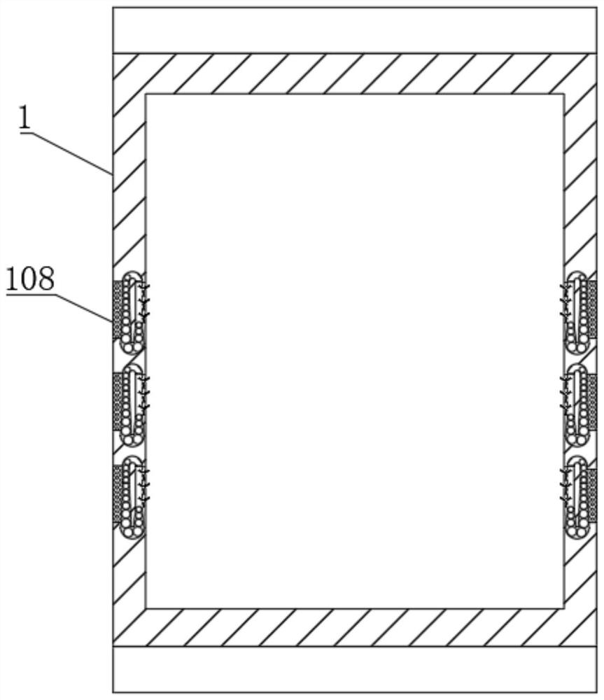
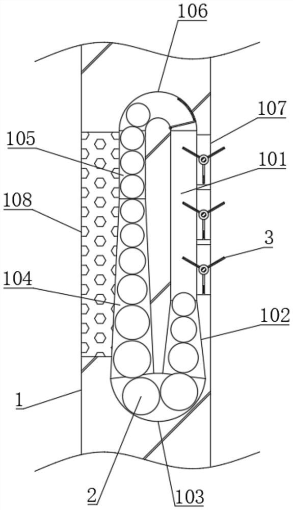
[0047] see figure 1 and figure 2 , an internal heat circulation type dehumidification and heat dissipation power distribution cabinet, including a cabinet body 1, the inner wall of the cabinet body 1 is provided with a plurality of evenly distributed closed airflow channels, and the closed airflow channels include descending channels arranged in sequence along a closed elliptical ring and connected to each other 101, the main gradual change channel 102, the main curve 103, the secondary gradual change channel 104, the choke channel 105 and the secondary curve 106, the descending channel 101 and the main gradual change channel 102 are located on the side close to the inside of the cabinet body 1, the secondary gradual change channel 104 and The choke channel 105 is located on the side close to the outside, the main curve 103 is located between the main gradual change channel 102 and the auxiliary gradual change channel 104, the auxiliary bend 106 is located between the drop ch...


PUM


Abstract

The invention discloses an internal heat circulation type dehumidification and heat dissipation type power distribution cabinet, belongs to the field of power distribution cabinets. The cabinet realizes the circulation flow of a heat dissipation settlement ball in a closed airflow channel through the heat absorption and heat release processes of the heat dissipation settlement ball, performs continuous heat dissipation on the interior of a cabinet body, and in the circulation flow process of the heat dissipation settlement ball, a rotary moisture reducing device is pushed to rotate through thevertical falling process of the heat dissipation settlement ball, so that the flowing of air flow in the cabinet body is accelerated, the heat dissipation efficiency can be improved, the heat in thecabinet body can be uniformly distributed, local moisture in the cabinet body is heated, the vaporization of the moisture is promoted, Water vapor can be discharged to the outside along with heat flow. In addition, the rotary moisture reduction device also has an absorption effect on vaporized moisture, the influence of the moisture on electrical equipment is reduced, and the absorbed water vaporcan be quickly diffused to the outside along with the air flow along with the rotary movement of the rotary moisture reduction device, so that the moisture reduction treatment on the interior of the cabinet body is realized.

Description

technical field [0001] The invention relates to the field of power distribution cabinets, more specifically, to an internal heat circulation type power distribution cabinet with dehumidification and heat dissipation. Background technique [0002] The power distribution cabinet (box) is divided into power distribution cabinet (box), lighting distribution cabinet (box), metering cabinet (box), and is the final equipment of the power distribution system. The power distribution cabinet is a general term for the motor control center. The power distribution cabinet is used in the occasions where the load is relatively scattered and there are few circuits; the motor control center is used in the occasions where the load is concentrated and there are many circuits. They distribute the electric energy of a certain circuit of the upper-level power distribution equipment to the nearest load. This level of equipment shall provide protection, monitoring and control of the load. [000...

Claims


Application Information

Patent Timeline
Patent Type & Authority Applications(China)
IPC IPC(8): H02B1/56H02B1/28B01D53/26
CPCB01D53/26B01D53/263B01D2257/80H02B1/28H02B1/565
Inventor 劳业鸿
Owner 劳业鸿
Why Eureka
Try Eureka