A passively assisted flexible bionic tension-compression body ankle-foot joint prosthesis based on air pressure changes

A technology of air pressure change and ankle joints, which is applied to artificial legs and other directions, can solve the problems of increasing the weight of prosthetics, damage, and unnecessary energy consumption of amputees, and achieve the effects of reducing wearing burden, saving maintenance costs, and ensuring stability

Active Publication Date: 2021-06-29
JILIN UNIV
View PDF6 Cites 0 Cited by
  • Summary
  • Abstract
  • Description
  • Claims
  • Application Information

AI Technical Summary

Problems solved by technology

However, due to the weight of the prosthetic device itself, the amputee will not only do more useless work when wearing it, but also increase the body load and increase the metabolic rate
And because amputees will suffer a series of additional muscle function damages such as excessive load on the lateral muscles of the limbs and increased load on the muscles at the end of the residual limb when wearing prostheses, which will cause more pain for the amputees. The hazards caused by accidents will be related to the standard of whether a prosthetic product is good or not
[0003] In addition, the traditional prosthetic design uses the spring-assisted function. This energy conversion method will not only increase the weight of the prosthesis, but also bring more meaningless energy consumption to the amputee. After the prosthesis, it cannot bring a truly continuous and natural power output to the human body's gait
[0004] Changing the overall material of the prosthesis from rigid to flexible will improve the above problems at the same time, so flexible prostheses, as an important future direction of prosthetics development, will have an incomparable role; but now researchers have research on flexible prostheses but very few

Method used


Image

  • A passively assisted flexible bionic tension-compression body ankle-foot joint prosthesis based on air pressure changes
  • A passively assisted flexible bionic tension-compression body ankle-foot joint prosthesis based on air pressure changes
  • A passively assisted flexible bionic tension-compression body ankle-foot joint prosthesis based on air pressure changes

Examples


Embodiment 1

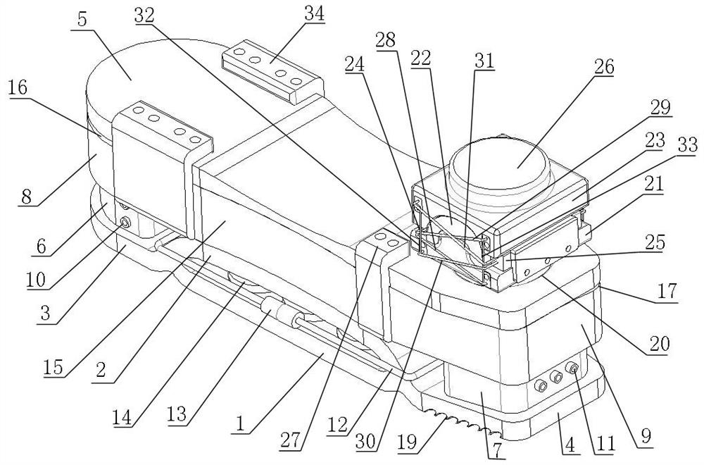
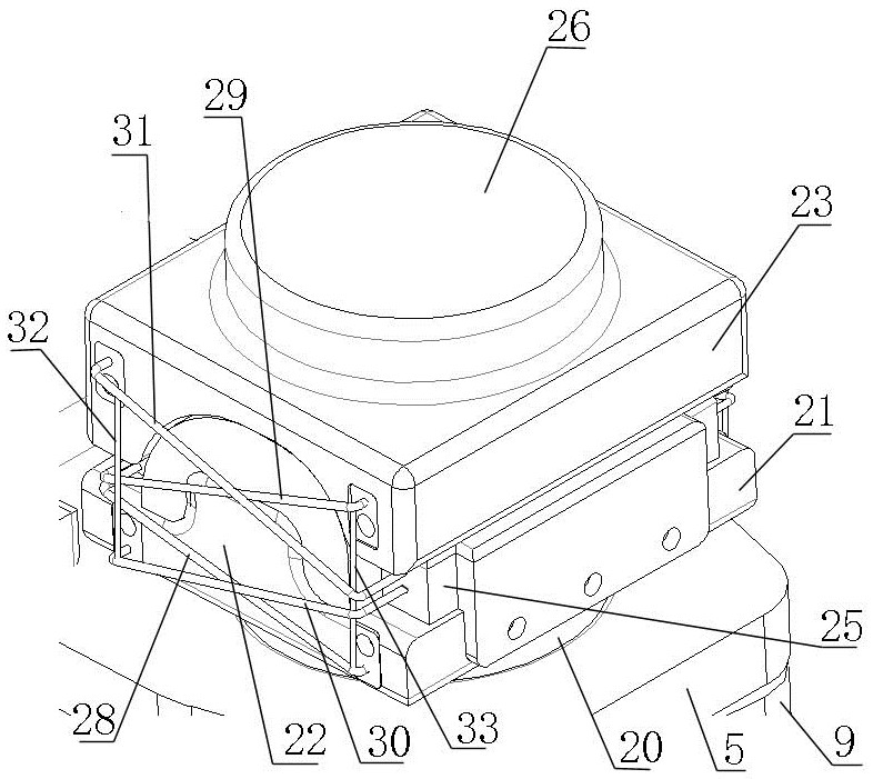
[0059] Such as Figure 1-2 As shown, the passively assisted flexible bionic tension-compression body ankle-foot joint prosthesis based on changes in air pressure includes ankle joints and feet;

[0060] The foot includes a foot support lower bottom plate 1, a foot support upper top plate 2, a foot support front assembly 3, a foot support rear assembly 4, a foot upper bearing plate 5, and a foot front air intake Cavity 6, rear extrusion air cavity 7 of foot, front air cavity 8 of component under foot force, rear air cavity 9 of component under force of foot;

[0061] The front end of the lower bottom plate 1 of the foot support is connected with the front assembly 3 of the foot support, and the rear end is connected with the rear assembly 4 of the foot support. The lower bottom plate 1 of the foot support is provided with an upper top plate of the foot support 2. The arch of the top plate 2 on the foot support simulates the arc of the human foot arch correspondingly;

[0062]...


PUM


Abstract

The invention discloses a passive-assisted flexible bionic tension-compression body ankle-foot joint prosthesis based on changes in air pressure, which includes an ankle joint and a foot; the foot includes a foot support lower bottom plate, a foot support upper top plate, a foot Foot support front assembly, foot support rear assembly, foot upper bearing plate, foot front air cavity, foot rear extrusion air cavity, foot force middle component front air cavity, foot force middle component Rear air cavity. In the bionic design of the flexible prosthesis of the present invention, the method of applying the working principle of the tension and compression body of the human skeleton to the design of the prosthesis is more in line with the natural characteristics of the human body, can effectively improve the natural gait of the human body, and provides a new method for the design of flexible prostheses today. Feasible ideas and methods to help the development of future prosthetics design.

Description

technical field [0001] The invention relates to the field of ankle-foot joint prostheses, in particular to a passive-assisted flexible bionic tension-compression body ankle-foot joint prosthesis based on changes in air pressure. Background technique [0002] Nowadays, with the advancement and development of science and technology, people can install prosthetic limbs to replace their feet after amputation, which can support the human body and assist in walking. However, due to the weight of the prosthetic device itself, the amputee will not only do more useless work when wearing it, but also increase the body load and increase the metabolic rate. And because amputees will suffer a series of additional muscle function damages such as excessive load on the lateral muscles of the limbs and increased load on the muscles at the end of the residual limb when wearing prostheses, which will cause more pain for the amputees. The hazards that occur will be related to the standard of w...

Claims


Application Information

Patent Timeline
Patent Type & Authority Patents(China)
IPC IPC(8): A61F2/66
CPCA61F2/6607A61F2002/6614A61F2002/665
Inventor 王坤阳靳剑桥任雷钱志辉修豪华梁威任露泉
Owner JILIN UNIV
Why Eureka
Try Eureka