Die and method for front and back deep drawing of double-layer cylindrical parts

A technology of forming dies and double-layer cylinders, which is applied in the direction of forming tools, manufacturing tools, metal processing equipment, etc., can solve the problems of one-time stamping and forming of positive and negative deep drawing structures, easy cracking of plates, and high processing costs, so as to avoid wrinkling , reduce residual stress, improve the effect of forming limit

Active Publication Date: 2021-08-31
YANSHAN UNIV
View PDF14 Cites 1 Cited by
  • Summary
  • Abstract
  • Description
  • Claims
  • Application Information

AI Technical Summary

Problems solved by technology

However, when the ordinary stamping method is used for processing, it is impossible to complete the stamping of the positive and negative deep-drawing structures at one time, and the parts need multiple sets of molds and processes to form. Such a processing method has high processing costs and poor economic benefits.
[0003] At present, the positive and negative deep drawing method used to make curved surface parts or parts with small drawing coefficient and large drawing change degree is generally to use a punch or die with a slightly larger diameter for positive drawing, and punch out a slightly larger diameter. The cylindrical blank, and then use a small diameter punch or die to reverse the blank, or punch the hole first and then process the outer circle of the part. Some of these methods need to use multiple sets of molds to deep-draw the workpiece, and some When the workpiece is reverse-drawn, the plate near the tangent between the positive-drawing punch or the concave film chamfer and the cylinder wall is prone to breakage, and it is not easy to process the workpiece that requires the flange edge

Method used


Image

  • Die and method for front and back deep drawing of double-layer cylindrical parts
  • Die and method for front and back deep drawing of double-layer cylindrical parts
  • Die and method for front and back deep drawing of double-layer cylindrical parts

Examples


Embodiment 1

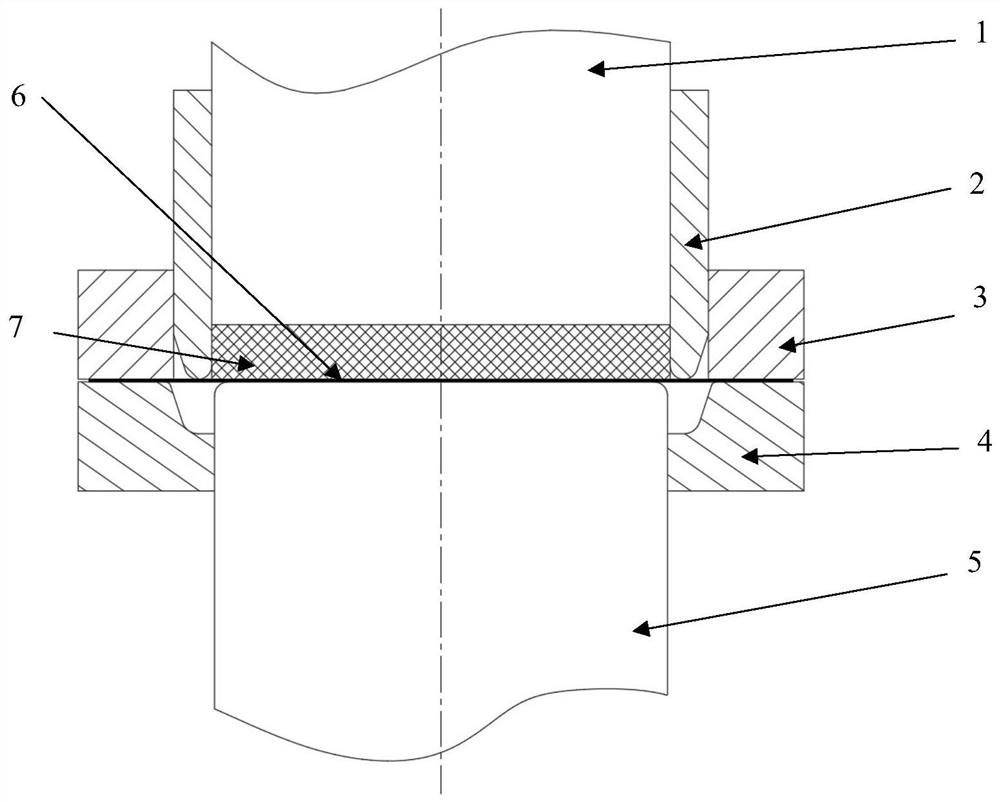
[0050] see figure 1 , which shows a schematic cross-sectional front view of the double-layer tubular part before processing the front and back drawing dies in Embodiment 1 of the present invention. The mold includes a second part and a first part which are arranged up and down oppositely and matched with each other, the first part is located below the second part, and the plate 6 for making the double-layer tubular part is located in the middle of the first part and the second part;

[0051] The first part is the lower end of the mold, including: a cylindrical punch 5 and a die 4 fixed on the forming equipment or mold fixture. Punch 5 is cylindrical, and the shape of its upper end is conical shape, and its diameter is identical with the inner diameter of the double-layer cylindrical part to be made. The die 4 is an annular part with a first central through hole, the diameter of the first central through hole is greater than or equal to the outer diameter of the punch 5 , and ...

Embodiment 2

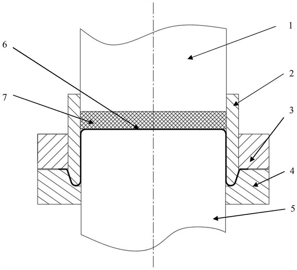
[0060] see Figure 5 , which shows a schematic cross-sectional front view of the double-layer tubular part before processing the front and back drawing dies in Embodiment 2 of the present invention. The mold includes a second part and a first part which are arranged up and down oppositely and matched with each other, the first part is located below the second part, and the plate 6 for making the double-layer tubular part is located in the middle of the first part and the second part;

[0061] The first part is the lower end of the mold, including: a cylindrical punch 5 and a die 4 fixed on the forming equipment or mold fixture. The punch 5 is cylindrical, the shape of its upper end is conical, and there is a spherical bulge in the middle of the truncated end face. The specific size of the spherical bulge is related to the parts to be processed. The inner diameter of parts is the same, and the die 4 is an annular part with a first central through hole, the diameter of the firs...

Embodiment 3

[0069] see Figure 8 , which shows a schematic cross-sectional front view of the double-layer tubular part before processing the front and back drawing dies in Embodiment 3 of the present invention. The mold includes a second part and a first part which are arranged up and down oppositely and matched with each other, the first part is located below the second part, and the plate 6 for making the double-layer tubular part is located in the middle of the first part and the second part;

[0070] The first part is the lower end of the mold, including: a cylindrical punch 5 and a die 4 fixed on the forming equipment or mold fixture. The punch 5 is cylindrical, and its upper end is in the shape of a truncated cone. There is a truncated cone-shaped protrusion in the middle of the truncated cone-shaped end surface. The specific size of the truncated cone-shaped protrusion is related to the parts to be processed. The inner diameter of the shaped parts is the same. The die 4 is an ann...


PUM


Abstract

The invention discloses a front and back drawing forming die and method of a double-layer cylindrical part. The lower end of the mold has a punch and a die, the die has a deep drawing groove, the upper end of the die has a back pressure punch and a convex ring, and the convex ring is covered with a blank holder. When forming positive and negative deep drawing, the plate is placed on the mold. At the beginning, the upper end of the punch is flush with the bottom end of the blank holder, and the plate is placed between the punch and the convex ring. The convex ring is stationary, and the bottom punch moves upward. The drawn sheet flows into the convex ring, and the sheet gradually covers the punch under the action of the back pressure of the back pressure punch, the downward pressure of the convex ring and the upward pressure of the punch. When the punch rises to the specified stroke, it begins to fall. When the convex ring goes down to draw the sheet, under the pressure of each part in the mold, the thickness of the sheet covering the punch part remains basically unchanged, while the sheet below the blank holder continues to be fed until the sheet is attached to the die, and the forming is terminated . The invention saves molds, shortens the processing procedure of workpieces and improves production efficiency.

Description

technical field [0001] The invention relates to the technical field of metal plates, and more specifically relates to a front and back drawing die and method for a double-layer cylindrical part. Background technique [0002] In the fields of automobiles, electronics, aviation, etc., the shape of some metal parts to be processed is relatively complex, and it is difficult to form one-time spinning by the spinning process. Parts with relatively high surface quality requirements are difficult to process, and the blank of the workpiece can be manufactured by stamping. However, when the ordinary stamping method is used for processing, it is impossible to complete the one-time stamping of the positive and negative deep-drawing structures, and the parts need multiple sets of molds and processes to form. Such a processing method has high processing costs and poor economic benefits. [0003] At present, the positive and negative deep drawing method used to make curved surface parts o...

Claims


Application Information

Patent Timeline
Patent Type & Authority Patents(China)
IPC IPC(8): B21D37/10B21D22/22
CPCB21D22/22B21D37/10
Inventor 曹秒艳庞世缘胡晗姚盼亮韩旭斌
Owner YANSHAN UNIV
Why Eureka
Try Eureka