Efficient locating system of intelligent industrial robot
An industrial robot and positioning system technology, applied in the field of high-efficiency positioning systems for intelligent industrial robots, can solve problems such as inaccurate processing of workpieces by robots, slow positioning speed, and unstable positioning systems
- Summary
- Abstract
- Description
- Claims
- Application Information
AI Technical Summary
Problems solved by technology
Method used
Image
Examples
Embodiment 1
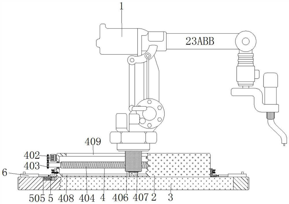
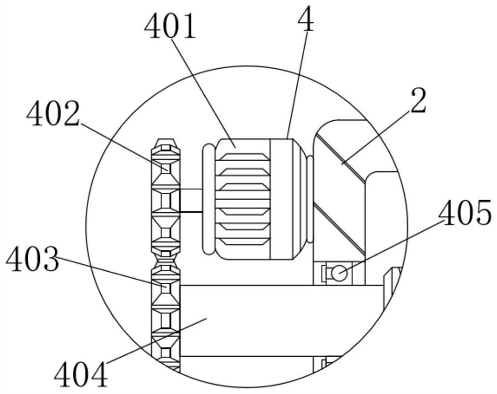
[0034]An efficient positioning system for an intelligent industrial robot, comprising an industrial robot 1, a casing 2 is arranged below the industrial robot 1, and a positioning mechanism 4 is installed inside the casing 2, and the positioning mechanism 4 includes a motor 401, a first gear 402, a second Gear 402, threaded rod 404, bearing 405, vertical block 406, first slide block 407, first chute 408 and groove 409, the right end of motor 401 is fixedly connected with the top left end of housing 2, the output shaft of motor 401 is connected with The middle of the right end of the first gear 402 is fixedly connected, and the output shaft of the motor 401 drives the first gear 402 to rotate forward and reverse at a uniform speed. The meshing force makes the second gear 403 rotate positively and negatively at a uniform speed. The middle of the right end of the second gear 403 is fixedly connected with the left end of the threaded rod 404. The threaded rod 404 is driven to rota...
Embodiment 2
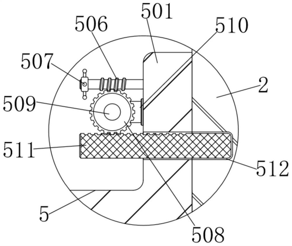
[0036] As an option, see figure 1 , 3 And 4, the intelligent industrial robot positioning system, the upper left and right sides of the bottom plate 3 are equipped with a fixed mechanism 5, the fixed mechanism 5 includes a splint 501, a handle 502, a second slider 503, a second chute 504, a spring 505, and a worm 506 , rotating rod 507, worm gear 508, pin shaft 509, support rod 510, cross bar 511 and draw-in groove 512, the right end of splint 501 and the lower left end of housing 2 fit together, and the bottom left side of splint 501 is provided with handle 502, A handle 502 is affixed to the lower left end of the splint 501, a second slider 503 is arranged in the middle of the bottom of the splint 501, the middle of the bottom of the splint 501 is fixedly connected with the top of the second slider 503, and the second slider 503 is connected to the second slider 503. The groove 504 is slidingly clamped, and the second sliding groove 504 is provided on the upper inner wall o...
Embodiment 3
[0040] The application of the intelligent industrial robot positioning system, when using the intelligent industrial robot positioning system, first manually drag the handles 502 on both sides to the outside to make the splints 501 on both sides pass through the second sliders 503 on the second sides of the bottom plate 3 respectively. The chute 504 slides to the outside, and the second sliders 503 on both sides move to the outside to compress the springs 505 on both sides, which can be adjusted according to the specifications of the housing 2 below the industrial robot 1. Otherwise, the elasticity of the springs 505 can make both sides The splint 501 clamps and fixes the shell 2 on the bottom plate 3, and the rotating rod 507 on both sides makes the worm 506 on both sides rotate on both sides of the splint 501 through the inner rubber pad, and the meshing between the worm wheel 506 and the worm wheel 508 The force makes the worm gears 508 on both sides rotate on the support ro...
PUM
 Abstract
Description
Claims
Application Information
 - R&D
- Intellectual Property
- Life Sciences
- Materials
- Tech Scout
- Unparalleled Data Quality
- Higher Quality Content
- 60% Fewer Hallucinations
Browse by: Latest US Patents, China's latest patents, Technical Efficacy Thesaurus, Application Domain, Technology Topic, Popular Technical Reports.
© 2025 PatSnap. All rights reserved.Legal|Privacy policy|Modern Slavery Act Transparency Statement|Sitemap|About US| Contact US: help@patsnap.com


