Centrifugal dehydrator for rapeseed oil refining technology

A centrifugal dehydrator, rapeseed oil technology, applied in the direction of fat oil/fat refining, filtration and separation, separation methods, etc., can solve the problems of centrifuge cylinder hole clogging, affecting oil discharge, etc.

Inactive Publication Date: 2021-01-05
SICHUAN DEYANG NIANFENG FOOD
View PDF0 Cites 5 Cited by
  • Summary
  • Abstract
  • Description
  • Claims
  • Application Information

AI Technical Summary

Problems solved by technology

[0009] However, the oil usually contains certain impurities or solids. When the centrifugal cylinder rotates, it is very easy to throw it on the wall of the centrifugal cylinder, and under the action of centrifugal force, it adheres to the centrifugal cylinder, and it is easy to make the holes on the centrifugal cylinder Slots and other structures are blocked, affecting oil discharge, etc.

Method used


Image

  • Centrifugal dehydrator for rapeseed oil refining technology
  • Centrifugal dehydrator for rapeseed oil refining technology
  • Centrifugal dehydrator for rapeseed oil refining technology

Examples


Embodiment 1

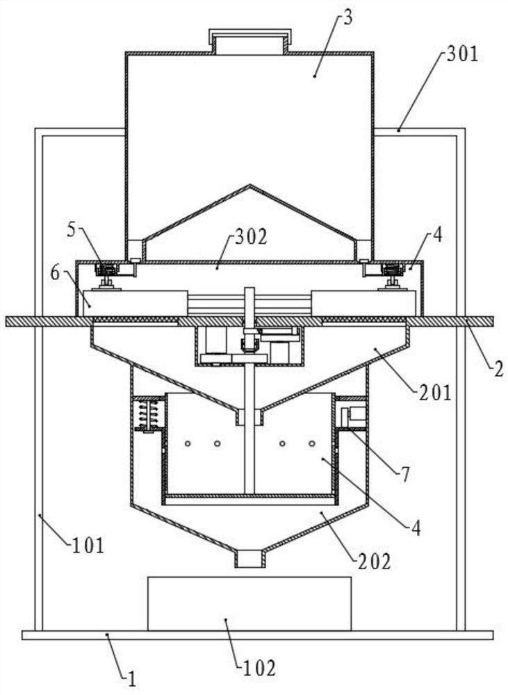
[0050] Please refer to the accompanying drawings, the present invention provides a technical solution: a centrifugal dehydrator for rapeseed oil refining technology, including a base 1, a workbench 2 and a storage box 3, and the workbench 2 is fixed by a first support rod 101 On the top of the base 1, the material storage box 3 is fixed on the top of the workbench 2 through the second support rod 301;

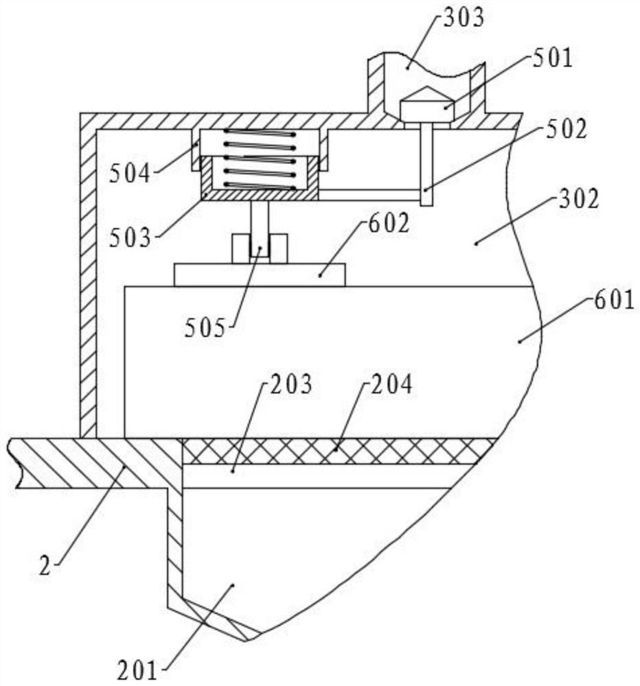
[0051] The top surface of the workbench 2 is provided with an annular groove 203, and an annular filter screen 204 is fixed in the annular groove 203, and a filter box 302 is fixed on the position corresponding to the annular filter screen 204 on the workbench 2, and the bottom of the material storage box 3 is along the circumferential direction. A plurality of feeding pipes 303 are uniformly fixed, and the feeding pipes 303 communicate with the filter box 302, and the position corresponding to each feeding pipe 303 in the filter box 302 is provided with a first sealing assembly...

Embodiment 2

[0054] The structure of this embodiment is basically the same as that of Embodiment 1, the difference is that the first sealing assembly 5 includes a sealing plug 501 arranged in the feeding tube 303, the top surface of the sealing plug 501 is set as a conical surface, and the outer ring of the bottom surface is set It is a conical surface, and the nozzle of the feeding pipe 303 is correspondingly provided with a conical surface, and the bottom surface of the sealing plug 501 is connected with the conical surface at the nozzle, and the bottom of the sealing plug 501 is fixed with a moving rod 502, and the moving rod 502 The outside of the bottom end of the filter box 503 is fixed with a moving cylinder 503 through a cross bar, and the top surface of the filter box 302 is correspondingly fixed with a fixed cylinder 504. A spring is arranged between the surfaces, and the bottom end of the moving cylinder 503 is fixed with a vertical push rod 505, and the bottom end of the push ro...

Embodiment 3

[0069] The structure of this embodiment is basically the same as that of Embodiment 1, except that a filter press assembly 9 is provided at a position between two adjacent feeding pipes 303 in the filter box 302, and the filter press assembly 9 includes a pressing plate 901, and the pressing plate Both sides of the top surface of 901 are fixed with vertical slide bar 904 symmetrically, the top of slide bar 904 passes through the top surface of filter box 302 and is fixed with spring plate 905, and the top surface of spring plate 905 and filter box 302 is provided with There is a spring, and the top surface of the inner cavity of the filter box 302 is symmetrical to the position in the middle of the pressure plate 901 and is rotationally connected with two intermeshing connecting gears 903, one of which is connected with a motor, and the two connecting gears 903 are fixed with Pressing rod 902, and the two pressing rods 902 are symmetrically inclined, and the bottom end of press...


PUM


Abstract

The invention discloses a centrifugal dehydrator for a rapeseed oil refining technology in the technical field of rapeseed oil refining. The centrifugal dehydrator comprises a base, a workbench and astorage box, wherein the workbench is provided with a filter box, an annular filter screen and a cleaning assembly, the bottom of the storage box is provided with a plurality of discharging pipes anda first sealing assembly, the first sealing assembly is correspondingly connected with the cleaning assembly, a collecting hopper and a fixing box are arranged below the fixing table, and a centrifugal cylinder and a second sealing assembly are arranged in the fixing box. According to the invention, oil is filtered through the annular filter screen, solid dregs and the like in the oil are removed,impurities on the annular filter screen are cleaned through the cleaning assembly, and the impurities are prevented from being accumulated at the discharging position; the first sealing assembly intermittently opens the discharging pipe through an ejector block in the cleaning assembly, so that intermittent discharging is achieved, and the oil amount is controlled; and through transmission of themotor, the first gear and the second gear, the second rotating shaft and the centrifugal cylinder rotate, so that oil and water are separated.

Description

technical field [0001] The invention relates to the technical field of rapeseed oil refining, in particular to a centrifugal dehydrator used in the rapeseed oil refining technology. Background technique [0002] Rapeseed oil is a kind of edible oil and one of the main edible oils in my country. It is mainly produced in the Yangtze River Basin, Southwest, Northwest and other places, and its output ranks first in the world. The human body has a high absorption rate of rapeseed oil, which can reach 99%. Therefore, the unsaturated fatty acids such as linoleic acid and vitamin E and other nutrients contained in it can be well absorbed by the body, and have certain effects of softening blood vessels and delaying aging. [0003] Since the raw material for oil extraction is the seed of a plant, it generally contains a certain amount of seed phospholipids, which is very important for the development of blood vessels, nerves, and brain. Rapeseed oil has little or no cholesterol, so p...

Claims


Application Information

Patent Timeline
Patent Type & Authority Applications(China)
IPC IPC(8): C11B3/00B01D36/00
CPCB01D36/008C11B3/001
Inventor 王安体张静李森凤
Owner SICHUAN DEYANG NIANFENG FOOD
Why Eureka
Try Eureka