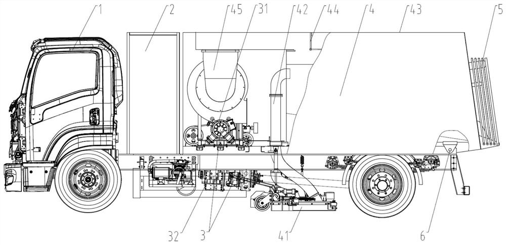
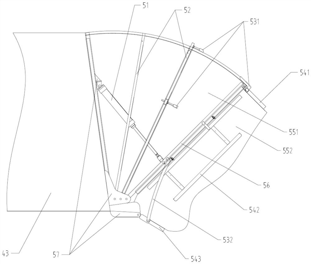
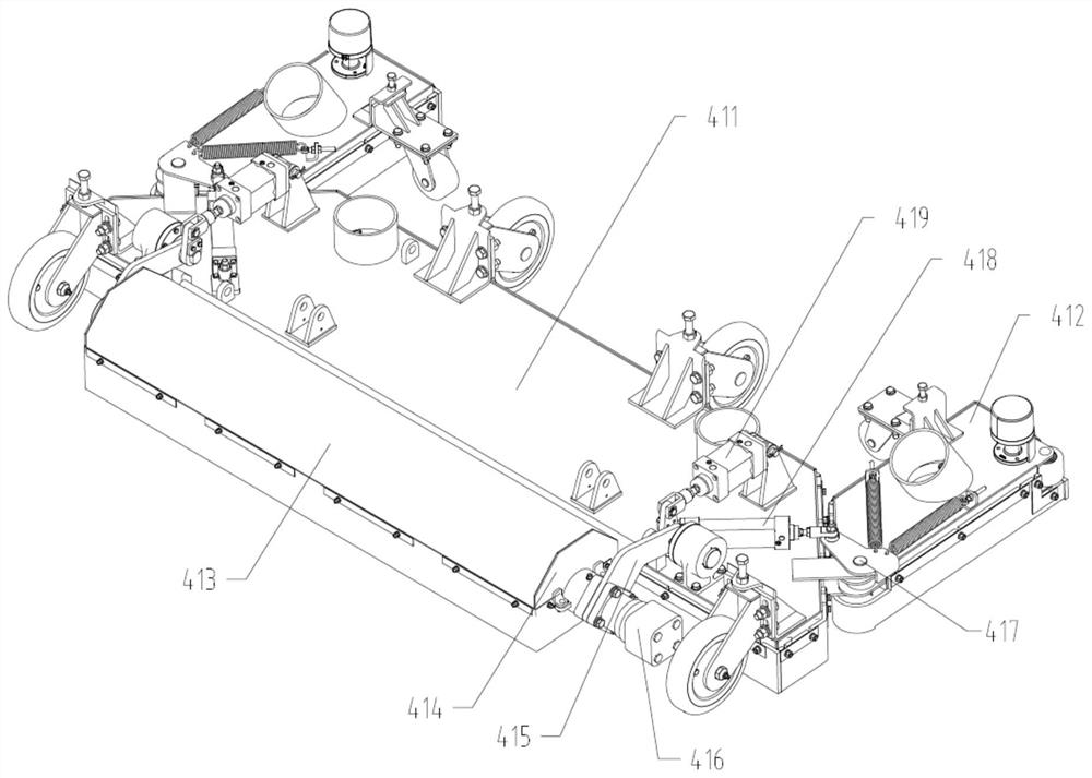
Environment-friendly vacuum sweeper

A vacuum cleaning vehicle and environmental protection technology, which is applied in road cleaning, construction, cleaning methods, etc., can solve the problems of large emission pollution and noise pollution, unclean cleaning, and difficult inhalation of cleaning vehicles, so as to achieve strong adaptability to the working environment, Effects of improving working efficiency and increasing working width

Pending Publication Date: 2021-01-05
SHAANXI AUTOMOBILE GROUP
View PDF0 Cites 1 Cited by
  • Summary
  • Abstract
  • Description
  • Claims
  • Application Information

AI Technical Summary

Problems solved by technology

And the known cleaning vehicle mainly sweeps the rubbish on the ground to the below of the suction nozzle body by the sweeping disc, and the rubbish is sucked in the dustbin by the suction nozzle, but when there is no watering operation in winter, the dust is relatively large; The core component of road vehicles sucking garbage is the only entrance for garbage and sand dust to be sucked up. Its performance is directly related to the cleaning ability of the sweeper
Ordinary pure suction vacuum discs can only meet the general road operation conditions, but there are still some shortcomings: when there is a lot of garbage and dust on the ground and most of them are hardened, the cleaning is not clean; there is large volume of garbage on the ground (such as mineral water bottles) ), it is not easy to inhale; when the operating speed increases, the net rate is low
The power units of traditional sweeping vehicles basically adopt dual-engine technology, and some new sweeping vehicles adopt single-engine technology. It is still very large, and it is far from meeting the work needs of the sanitation department

Method used


Image

  • Environment-friendly vacuum sweeper
  • Environment-friendly vacuum sweeper
  • Environment-friendly vacuum sweeper

Examples


Embodiment Construction

[0029] The above and other technical features and advantages of the present invention will be described in more detail below in conjunction with the accompanying drawings.

[0030]In describing the present invention, it should be understood that the terms "center", "longitudinal", "transverse", "length", "width", "thickness", "upper", "lower", "front", " Back", "Left", "Right", "Vertical", "Horizontal", "Top", "Bottom", "Inner", "Outer", "Clockwise", "Counterclockwise", "Axial", The orientations or positional relationships indicated by "radial", "circumferential", etc. are based on the orientations or positional relationships shown in the drawings, and are only for the convenience of describing the present invention, rather than indicating or implying that the referred device or element must have a specific orientation, are constructed and operate in a particular orientation and therefore are not to be construed as limiting the invention.

[0031] In addition, the terms "firs...


PUM


Abstract

The invention provides an environment-friendly vacuum sweeper. The environment-friendly vacuum sweeper comprises a pure electric vehicle body, an air path system, a discharging dust suppression device, a power transmission system and a battery. The air path system comprises a dust suction device, an air pipe, a dust removal device, a conversion door and a fan, the dust suction device is arranged at the bottom of the vehicle body and communicated with the dust removal device through the air pipe, the dust removal device is communicated with the air suction port of the fan through an air duct, and the conversion door is arranged between the air duct and the dust removal device. The conversion door can selectively seal the air outlet of a dry dust flow channel or the air outlet of a wet dustflow channel, so that dust-carrying airflow from the dust collection device selectively passes through a dry dust removal space or a wet dust removal space to remove dust. The dust removal device canbe arranged above the vehicle body in a lifting mode along a turnover shaft, and the discharging dust suppression device can be arranged at the rear end of the dust removal device in an unfolding andfolding mode; and the power transmission system comprises an upper power transmission system and a chassis power transmission system. The operation process is simple in operation, energy-saving, environment-friendly, zero-emission and low in noise.

Description

technical field [0001] The invention relates to the technical field of special vehicles for road cleaning, in particular to an environment-friendly dust collection vehicle. Background technique [0002] With the continuous development of the economy, the operation mode of urban and rural road sanitation has changed from the original manual operation to the current mechanical operation mode such as road sweepers, cleaning vehicles, and sprinklers. And the known cleaning vehicle mainly sweeps the rubbish on the ground to the below of the suction nozzle body by the sweeping disc, and the rubbish is sucked in the dustbin by the suction nozzle, but when there is no watering operation in winter, the dust is relatively large; The core component of road vehicles sucking garbage is the only entrance for garbage and sand dust to be sucked up. Its performance is directly related to the cleaning ability of the sweeper. Ordinary pure suction vacuum discs can only meet the general road o...

Claims


Application Information

Patent Timeline
Patent Type & Authority Applications(China)
IPC IPC(8): E01H1/08
CPCE01H1/0836
Inventor 王仁鹏赵强李温锋郭佳鹏朱阳赵增耀黄振峰雷波马莹曹晨强文艺刘友红
Owner SHAANXI AUTOMOBILE GROUP
Why Eureka
Try Eureka