Wall surface spraying device for building

A spraying device and construction technology, applied in construction, building construction, etc., can solve problems such as waste of plastering liquid, dripping liquid, potential safety hazards of plastering workers, etc., and achieve the effect of improving the use effect, simple structure, and good application prospects

Inactive Publication Date: 2021-01-05
李成信
View PDF0 Cites 1 Cited by
  • Summary
  • Abstract
  • Description
  • Claims
  • Application Information

AI Technical Summary

Problems solved by technology

[0003] For now, most of the existing wall painting devices use roller painting. For the top of the wall or high places, it is generally necessary to set up scaffolding for climbing and painting. There are certain safety hazards for the painting workers; Phenomenon, so that excess liquid slides down along the wall to cause waste of plastering liquid; and then proposes a wall spraying device for construction

Method used


Image

  • Wall surface spraying device for building
  • Wall surface spraying device for building
  • Wall surface spraying device for building

Examples


Embodiment 1

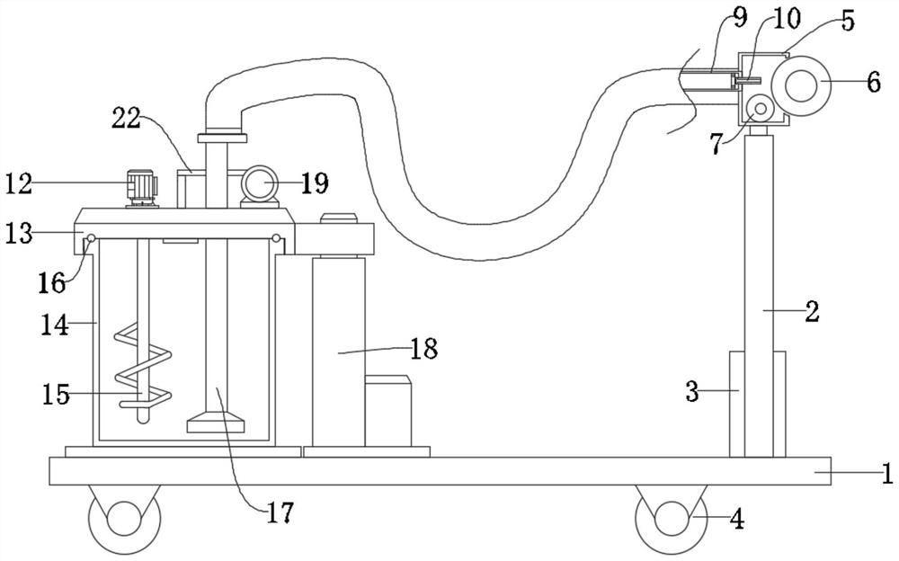
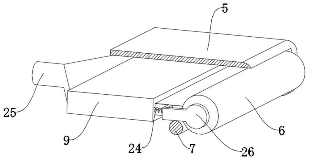
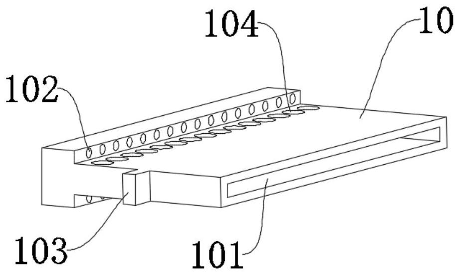
[0021]SeeFigure 1-3, A wall spraying device for construction, including a bottom plate 1, a paint bucket 14 and a spraying device are arranged on the bottom plate 1, an upper cover 13 is arranged above the paint bucket 14, and the upper cover 13 and the paint bucket 14 pass between The threaded connection further facilitates the replacement of the paint bucket 14; the spraying device includes a feeding assembly and a painting assembly, and the feeding assembly is arranged on the upper cover 13, and further provides paint for the painting assembly; The painting assembly described includes a discharge plate 9, a piston plate 10, a protective cover 5, a painting wheel 6, an absorption wheel 7 and a discharge pipe 25. One end of the discharge pipe 25 is connected to the supply assembly. The other end is connected to the discharge plate 9. The inside of the discharge plate 9 is a hollow structure, which further facilitates the filling of the discharge plate 9 with paint; the piston plate...

Embodiment 2

[0029]In order to avoid the precipitation and solidification of the paint in the paint bucket 14 and further affect the actual spraying effect, this embodiment has made the following improvements on the basis of the first embodiment. The improvement is that a stirring is arranged on the upper cover 13 The stirring device includes a motor 12 and a stirring rod 15. The motor 12 is fixedly installed on the upper cover 13, and the stirring rod 15 is fixedly connected with the rotating shaft of the motor 12, and the rotation of the motor 12 further drives the stirring rod The rotation of 15 in the paint bucket 14 realizes the mixing of paint, avoids solidification and mixing, and improves the actual use effect.

[0030]The working principle of this embodiment: the rotation of the motor 12 further drives the rotation of the stirring rod 15 in the paint bucket 14 to realize the stirring of the paint, avoid solidification and mixing, and improve the actual use effect.


PUM


Abstract

The invention discloses a wall surface spraying device for a building. The wall surface spraying device comprises a bottom plate, wherein a coating barrel and a spraying device are arranged on the bottom plate; an upper cover is arranged above the coating barrel; the upper cover is in threaded connection with the coating barrel; the spraying device comprises a feeding assembly and a brushing assembly; a piston plate is arranged in a discharging plate in a sliding manner; steps are fixedly connected to two sides of the piston plate; springs are arranged between the steps and the discharging plate; a bracket is connected to the steps; a brushing wheel is rotationally arranged on the bracket; a protective cover is fixedly connected to the discharging plate; and an absorption wheel is rotationally arranged on the protective cover. According to the device, the coating is sprayed onto the brushing wheel through a through hole I, a through hole II and a discharging hole during brushing, the brushing wheel is just attached to the absorption wheel, and the redundant coating is further adsorbed by the absorption wheel, so that the actual using effect is improved. Therefore, dropping liquid of the coating can be effectively prevented, and the device has excellent application prospects.

Description

Technical field[0001]The invention relates to the field of construction, in particular to a wall spraying device for construction.Background technique[0002]Buildings are exposed to wind, sun, rain, abrasion, corrosion, etc. for a long time, and the decoration surface of the building will be damaged; in order to protect the building from environmental impact and damage, it is necessary to spray paint on the surface of the building; the paint can not only protect the The surface of the coated object prevents the corrosion from external light, oxygen, chemical substances, solvents, etc., and improves the service life of the coated object.[0003]At present, most of the existing wall painting devices use rollers to paint, and scaffolding is generally required for the top of the wall or high places for ascending and painting. There are certain safety hazards for painting workers; at the same time, roller painting is easy to cause dripping. This phenomenon causes excess liquid to slide down...

Claims


Application Information

Patent Timeline
IPC IPC(8): E04F21/08E04F21/12
CPCE04F21/08E04F21/12
Inventor 李成信
Owner 李成信
Why Eureka
Try Eureka