Electromagnetic supporting type drilling and anchoring integrated machine and anchoring method
An all-in-one, electromagnetic technology, applied in drilling equipment and methods, rotary drilling rigs, drilling pipes, etc., can solve the problems of complex anchoring procedures, long operation time, low anchoring efficiency, etc., to improve anchoring efficiency, save time, The effect of saving anchoring costs
- Summary
- Abstract
- Description
- Claims
- Application Information
AI Technical Summary
Problems solved by technology
Method used
Image
Examples
Embodiment 1
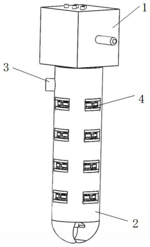
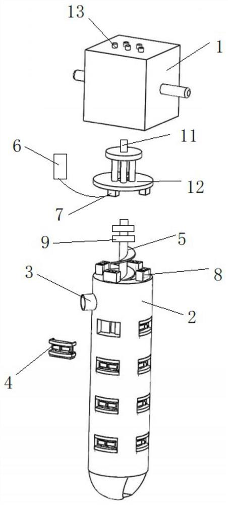
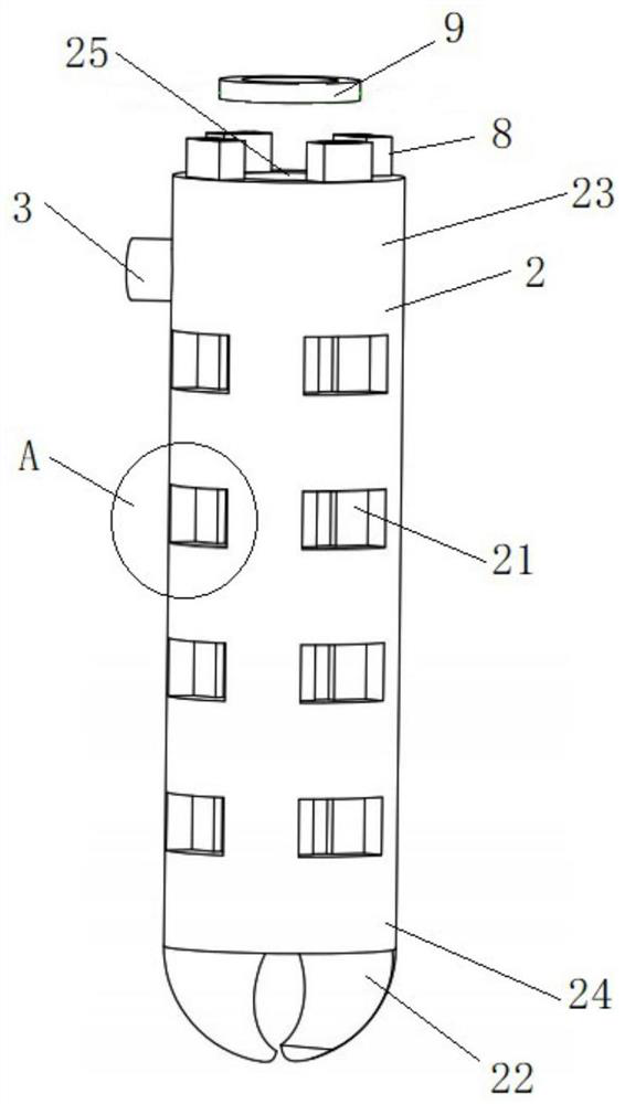
[0063] see Figure 1 to Figure 12 , the present invention provides an electromagnetic support type drilling and anchoring integrated machine, comprising a driving device 1, an anchor rod 2 and a plurality of electromagnetic anchoring devices 4 arranged on the outer peripheral wall of the anchor rod 2, and a plurality of electromagnetic anchoring devices 4 along the anchor rod 2 The circumferential direction is arranged in rows, at least two rows, and a plurality of electromagnetic anchoring devices 4 in each row are uniformly arranged in the axial direction of the anchor rods 2 . The electromagnetic anchoring device 4 is used to insert into the wall of the anchor hole to play a supporting role. The anchor rod 2 has opposite first end portions 23 and second end portions 24, and the anchor rod 2 extends between the first end portion 23 and the second end portion 24 in a rod shape. In this embodiment, the anchor rod 2 is a circle rod-shaped. The second end portion 24 of the anc...
Embodiment 2
[0077] The electromagnetic support type drill and anchor integrated machine described in this embodiment is based on the first embodiment, and the connection structure between the soil removal device 5 and the second gear shaft 124 is changed. In this embodiment, the soil removal device 5 and the second gear shaft 124 are changed. The second gear shaft 124 is connected through the locking sleeve 10, and the specific connection structure is as follows:
[0078] see Figure 13 and Figure 14 , The soil removal device 5 is fixedly connected with the second gear shaft 124 through the locking sleeve 10 . Specifically, the locking sleeve 10 is a hollow structure, specifically a cylindrical shape. One end is provided with a single row of card edges 102 pointing to the center, and the other end is an internal thread 101 structure. The card edge 71 can be an annular inner flange, or a plurality of arc-shaped flanges arranged at intervals along the circumferential direction of the lo...
PUM
 Abstract
Description
Claims
Application Information
 - R&D
- Intellectual Property
- Life Sciences
- Materials
- Tech Scout
- Unparalleled Data Quality
- Higher Quality Content
- 60% Fewer Hallucinations
Browse by: Latest US Patents, China's latest patents, Technical Efficacy Thesaurus, Application Domain, Technology Topic, Popular Technical Reports.
© 2025 PatSnap. All rights reserved.Legal|Privacy policy|Modern Slavery Act Transparency Statement|Sitemap|About US| Contact US: help@patsnap.com


