3D printing filling design method based on force flow pipe load path

A technology of 3D printing and design method, applied in the field of 3D printing, can solve the problems of reducing the strength and weakness of parts, and achieve the effect of improving the performance of parts, taking into account the accuracy and economy

Active Publication Date: 2021-01-05
TONGJI UNIV
View PDF11 Cites 0 Cited by
  • Summary
  • Abstract
  • Description
  • Claims
  • Application Information

AI Technical Summary

Problems solved by technology

[0003] The performance of the overall structure of the part is closely related to the shape, size, arrangement and distribution of the unit lattice or pores filled inside. At present, the internal filling structure of the part designed by 3D printing method mostly adopts linear grid or uniform honeycomb, etc., or based on Michel Topological structures such as trusses or principal stress lines, but there will be local weaknesses caused by problems such as hole defects, which will reduce the overall strength of the part

Method used


Image

  • 3D printing filling design method based on force flow pipe load path
  • 3D printing filling design method based on force flow pipe load path
  • 3D printing filling design method based on force flow pipe load path

Examples


Embodiment

[0045] The present invention proposes a 3D printing filling design method based on the load path of the force flow tube, and uses extrusion 3D printing technology for processing and manufacturing. There are many ways to define the load path. In this example, the force flow tube is specifically used. The load direction represented by (force tube), the definition of this load path can ensure constant load transmission in the main load direction, solve the local weakness caused by hole defects and other problems, and finally improve the overall strength of the part. The specific steps are as follows:

[0046] (1) Set the main force direction of the part According to the direction of the main force and the direction of the rectangular coordinate system Relationship: Create a computer 3D model;

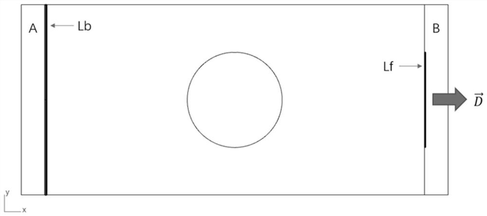
[0047] (2) Define the part clamping area A and the load application area B, and determine the constraint boundary Lb and the load boundary (or load point) Lf, such as figure 2 shown...


PUM


Abstract

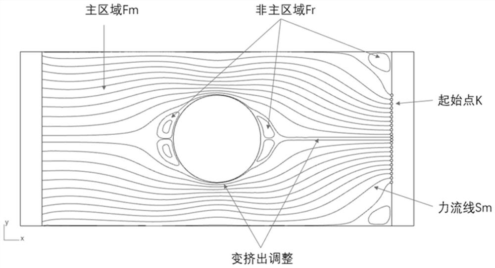
The invention relates to a 3D printing filling design method based on a force flow pipe load path. The method comprises the following steps of 1), obtaining the main stress direction of a part, constructing a three-dimensional model of the part according to the direction of a rectangular coordinate system, defining a part clamping region A and a load application region B, and determining a constraint boundary Lb and a load boundary or a load point Lf, 2) obtaining a force flow field direction of each node through finite element analysis and drawing a force flow field visualization graph, 3) setting the filling mass density and the caliber d of an extrusion head, and determining a load application distribution mode according to the type of the load to form an end point of a force streamline, 4) respectively drawing a force streamline Sm of the main region and a force streamline Sr of the non-main region, and 5) performing 3D printing according to the drawn force streamline. Compared with the prior art, the problem of local weakness caused by hole defects and the like is solved, and the overall strength of parts is effectively improved.

Description

technical field [0001] The invention relates to the technical field of 3D printing, in particular to a 3D printing filling design method based on the force flow tube load path. Background technique [0002] Additive manufacturing, also known as 3D printing technology, makes it possible to manufacture more complex and customized parts. 3D printing is different from traditional casting and cutting methods. Its manufacturing process is the simultaneous generation of materials and structures. , the material density is not necessarily dense filling. On the basis of designing the appearance structure size of the part and not changing the properties of the base material, using a structure such as a unit lattice or a thin-walled pore instead of dense filling can realize the lightweight design of the part and improve the strength. Performance, this new approach to part design and development has a very profound impact on additive manufacturing, helping to process parts with certain s...

Claims


Application Information

Patent Timeline
Patent Type & Authority Applications(China)
IPC IPC(8): G06F30/20G06F113/10G06F119/14
CPCG06F30/20G06F2113/10G06F2119/14
Inventor 王硕王玉
Owner TONGJI UNIV
Why Eureka
Try Eureka