Industrial power distribution cabinet

A power distribution cabinet, industrial technology, applied in substation/distribution device casing, animal husbandry, electrical components, etc., can solve the problems of inconvenient cabinet door fixing, electrical corrosion of power distribution cabinet, and inability to adjust in time.

Inactive Publication Date: 2021-01-05
滁州市胜威电力信息咨询有限公司
View PDF0 Cites 0 Cited by
  • Summary
  • Abstract
  • Description
  • Claims
  • Application Information

AI Technical Summary

Problems solved by technology

[0004] Although the above device can absorb shock, reduce temperature and dissipate heat, and monitor in real time, when facing the power distribution cabinet used in the boiler room, due to the special environment of the boiler room, such as high temperature and high humidity, if the outside of the cabinet is not protected, it will This will lead to the entry of moisture and corrosion of the electrical appliances inside the power distribution cabinet; even if the above-mentioned device can play a cooling role, it cannot be adjusted in a timely manner according to the needs of the environment, and the use effect is average. In addition, it is inconvenient to repair the cabinet door Fixed, it is easy to shake the door of the cabinet, causing accidental touch by the staff

Method used


Image

  • Industrial power distribution cabinet
  • Industrial power distribution cabinet
  • Industrial power distribution cabinet

Examples


Embodiment approach

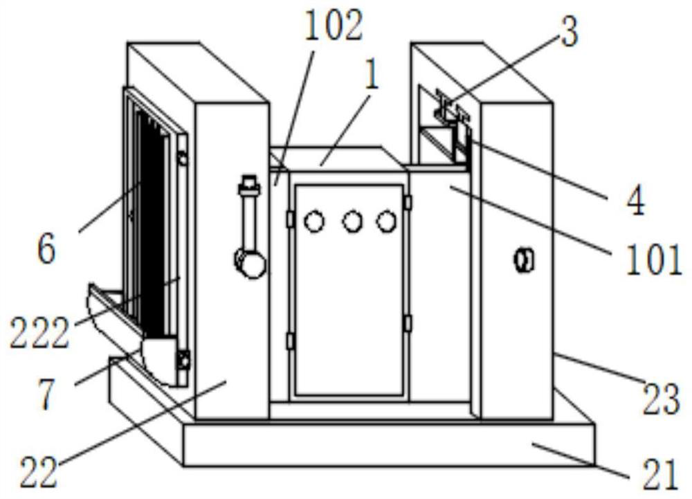
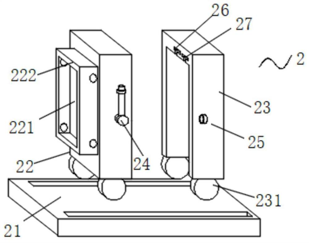
[0046] As an embodiment of the present invention, the two clamping mechanisms 3 on the left and right are symmetrical, and the clamping mechanism 3 includes an I-shaped inserting plate 31, a U-shaped card frame 32, a first movable plate 33, and a second movable plate. 34 and a butt plate 35, the I-shaped board 31 is clamped inside the first T-shaped slot 26, and the U-shaped card frame 32 is fixedly installed at the center outside the lower end of the I-shaped board 31, and the first The clamping of the movable plate 33 is connected to the inside of the U-shaped card frame 32, and the insides of the first movable plate 33 and the U-shaped card frame 32 are penetrated and connected with two-way bolts, and the second movable plate 34 is movably connected to the first movable plate 33. The rear end of the rear end is close to the position of the lower end, and the intersection of the first movable plate 33 and the second movable plate 34 is also penetrated and connected with two-w...


PUM


Abstract

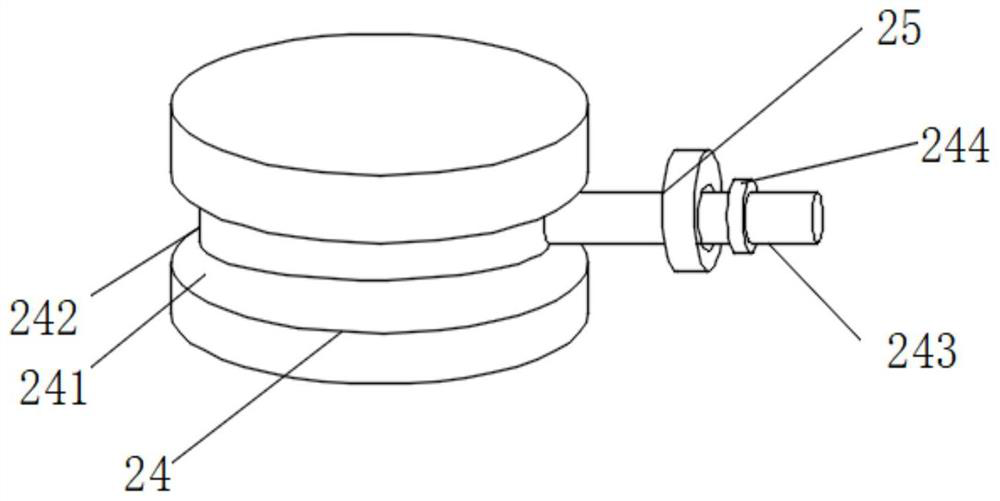
The invention discloses an industrial power distribution cabinet. The industrial power distribution cabinet comprises a cabinet body, an inner cabinet door and an outer cabinet door; the inner cabinetdoor is hinged to the front end of the outer surface of the right side of the cabinet body; the outer cabinet door is hinged to the position, close to the front end, of the outer surface of the leftside of the cabinet body; a first protection mechanism is movably connected to the exterior of the cabinet body; the first protection mechanism comprises a base, movable grooves, a first rectangular frame, a second rectangular frame, sliding wheels, limiting discs, limiting rings, first T-shaped grooves and second T-shaped grooves. According to the industrial power distribution cabinet of the invention, protection of the outer shell of the cabinet body can be enhanced, moisture is prevented from invading the surface of the cabinet body, damage to components in the cabinet body is reduced, maintenance personnel can be prevented from mistakenly touching buttons on the cabinet door to cause misoperation, maintenance is convenient, heat dissipation and cooling of the cabinet body are facilitated, and breakdown of the cabinet body caused by over-high temperature is avoided, the cabinet body is prevented from being contaminated by flocculent dust, a heat dissipation mechanism can be opened or closed according to needs, and the gnawing probability of a heat dissipation net and the cabinet body is reduced.

Description

technical field [0001] The invention relates to the technical field of power distribution cabinets, in particular to an industrial power distribution cabinet. Background technique [0002] The power distribution cabinet is the final equipment of the power distribution system. The power distribution cabinet is a general term for the motor control center. The power distribution cabinet is used in the occasions where the load is relatively scattered and there are few circuits; the motor control center is used in the occasions where the load is concentrated and there are many circuits. They distribute the electric energy of a certain circuit of the upper-level power distribution equipment to the nearest load. This level of equipment should provide protection, monitoring and control for the load. The power distribution cabinets currently used have certain defects and lack shock absorption functions. Damage, which reduces the service life of the power distribution cabinet, and ...

Claims


Application Information

Patent Timeline
Patent Type & Authority Applications(China)
IPC IPC(8): H02B1/30H02B1/28H02B1/54H02B1/38H02B1/56A01M29/30
CPCA01M29/30H02B1/28H02B1/30H02B1/38H02B1/54H02B1/565
Inventor 梁涛黄广顺
Owner 滁州市胜威电力信息咨询有限公司
Why Eureka
Try Eureka