Single-guide-rail glass lifter with variable motion resistance

A glass lifter and movement resistance technology, applied in the field of auto parts, can solve the problems of reducing the output efficiency of the lifter and increasing the risk of abnormal noise of glass lifter

Inactive Publication Date: 2021-01-08
DONGFENG MOTOR CORP HUBEI
View PDF6 Cites 1 Cited by
  • Summary
  • Abstract
  • Description
  • Claims
  • Application Information

AI Technical Summary

Problems solved by technology

[0003] In order to ensure the smoothness of the glass during the lifting process, it is necessary that the force F of the transmission rope on the slider is always a pulling force during the lifting process, and in order to ensure that F is always positive during the lifting process, there are currently two solutions: the first is Increase F 外 , such as increasing the interference amount or material hardness of the front / rear guide groove or the inner and outer water section of the window sill, although this solution can ensure the glass hovers, it increases the risk of abnormal noise when the glass is raised and lowered, and when the glass rises, increase the F 外 Reduce the output efficiency of the elevator; the second is to increase the F 内 , increase the clamping force on the guide rail through the interference fit of the reed and the friction plate in the upper and lower guide clips of the slider. Although this solution can ensure that the glass hovers, for the lifter, only for G 分 Part of the output is the effective output, the increased F 内 Reduced lifter output efficiency

Method used


Image

  • Single-guide-rail glass lifter with variable motion resistance
  • Single-guide-rail glass lifter with variable motion resistance
  • Single-guide-rail glass lifter with variable motion resistance

Examples


Embodiment Construction

[0027] The present invention will be further described below in conjunction with the accompanying drawings and embodiments.

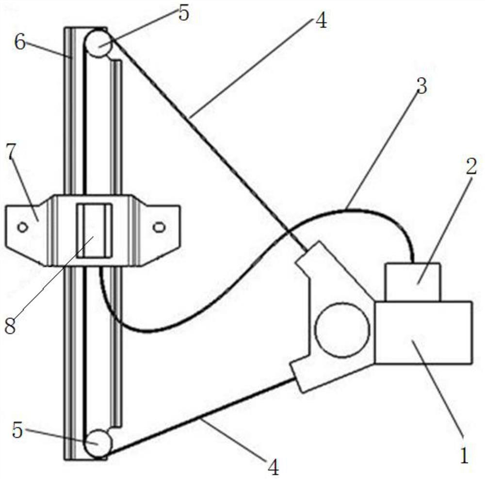
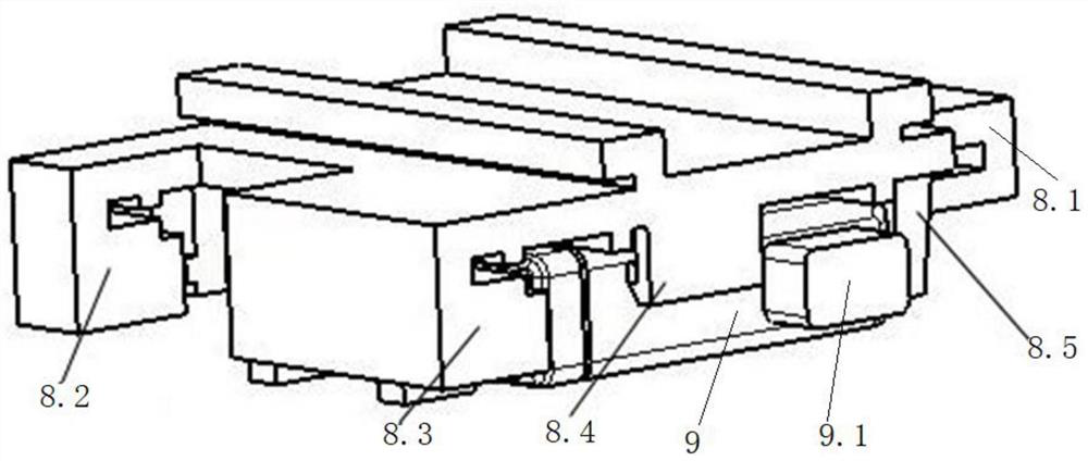
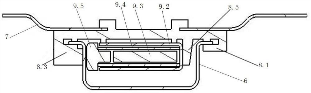
[0028] Such as Figure 1 to Figure 4 As shown, a single guide rail glass regulator with variable motion resistance includes an electronic control unit 2, a guide rail 6, a slider set on the guide rail 6, and a motor 1 that drives the slider up and down along the guide rail 6 through a transmission rope 4. The block is provided with installation structure and guiding structure (8.1, 8.2 and 8.3), and the variable pressure assembly 9 is installed on the installation structure. The spring 9.4 and the pressure head 9.5 on the 9.3, the spring 9.4 always presses the pressure head 9.5 on the guide rail 6, and the electromagnet 9.3 can attract the pressure head 9.5 to reduce the pressing force of the pressure head 9.5 on the guide rail 6. The guide structure (8.1, 8.2 and 8.3) are slidingly matched with the guide rail 6 and the frictional resistance to the gui...


PUM


Abstract

The invention discloses a single-guide-rail glass lifter with variable motion resistance. The single-guide-rail glass lifter comprises an electric control unit, a guide rail, a sliding block arrangedon the guide rail and a motor driving the sliding block to ascend and descend along the guide rail through a transmission rope, wherein the sliding block is provided with an installation structure anda guide structure; the installation structure is provided with a variable pressure assembly; the variable pressure assembly comprises a shell, an electromagnet located in the shell, a spring arrangedon the electromagnet in a sleeving manner and a pressing head; the spring presses the pressing head on the guide rail all the time; the electromagnet can attract the pressing head in the power-on state, and therefore the pressing force of the pressing head on the guide rail is relieved; the guide structure is in sliding fit with the guide rail, and the friction resistance of the guide rail duringsliding is far smaller than that of the pressing head on the guide rail; when the motor stops, the sliding block can suspend; and the electric control unit is electrically connected with the motor and the electromagnet. According to the single-guide-rail glass lifter, glass ascending and descending smoothness is guaranteed, the output efficiency is improved, the overall cost and the vehicle doorsystem weight are reduced, the design and arrangement space difficulty is lowered, and the abnormal sound risk during glass ascending and descending is avoided.

Description

technical field [0001] The invention belongs to the field of auto parts, in particular to a single guide rail glass lifter with variable movement resistance. Background technique [0002] The car door glass is raised, lowered and hovered through the glass lifter, in which the front and rear edges of the glass fit in the front / rear guide grooves respectively, the bottom edge of the glass is installed on the slider, and the slider fits on the guide rail, and the glass lifts The motor of the device drives the slider and the glass to move up and down along the guide rail through the transmission rope. The car door glass is mainly subjected to the following forces in the process of rising and falling: the component force G of the overall gravity of the glass and the slider along the direction of the guide rail 分 , Frictional resistance F between the glass and the front / rear guide groove and water cut inside and outside the window sill 外 (specifically including the frictional re...

Claims


Application Information

Patent Timeline
IPC IPC(8): E05F15/695E05D13/00E05D15/16B60J1/17
CPCB60J1/17E05D13/00E05D15/165E05Y2900/55E05F15/695
Inventor 杨飘刘颖文黄芹郑明贵张景煌
Owner DONGFENG MOTOR CORP HUBEI
Why Eureka
Try Eureka