Butt joint type range hood

A range hood, docking technology, applied in the direction of removing oil fume, heating method, household heating, etc., can solve the problems of smoke easily escaping to the outside, difficult to completely remove oil fume, time-consuming and laborious, etc., to improve the effect of smoke exhaust, The effect of reducing the volume of the smoke shell and improving the smoke collection effect

Active Publication Date: 2021-01-08
中山市博泰电器有限公司
View PDF5 Cites 0 Cited by
  • Summary
  • Abstract
  • Description
  • Claims
  • Application Information

AI Technical Summary

Problems solved by technology

[0003] Most of the range hoods on the market are monolithic. During installation, the range hood is heavy, and the large size causes troubles for installation, which is time-consuming and labor-intensive. However, most of the range hoods need to be disassembled, cleaned or repaired by disassembling the combined parts. It is found that The problem requires more processes and takes longer
[0004] In addition, the smoke exhaust function of the range hood during use is based on the smoke guidance of the negative pressure airflow. Difficult to achieve complete exclusion of oil fume

Method used


Image

  • Butt joint type range hood
  • Butt joint type range hood
  • Butt joint type range hood

Examples


Embodiment 1

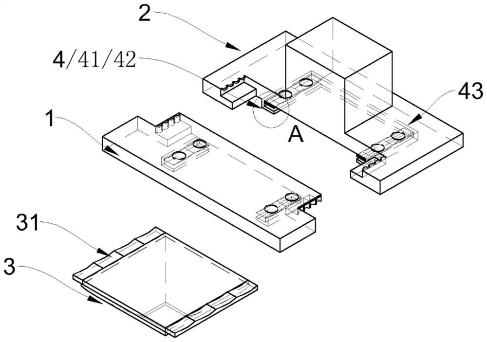
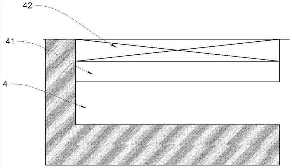
[0029] Such as Figure 1-Figure 3 Shown: a docking range hood, including the first half body 1, the second half body 2, the filter system 3 (the filter system 3 includes the filter screen in the mesh cover); the operation panel is located in the first half body 1 Above; the smoke exhaust pipe, fan system, and power system are located in the second half body 2, and the second half body 2 is fixed on the wall; There is an electrical docking interface between the operation panel and the power system (if the operation panel connected to the power system is placed on the second half body 2, there is no need to add a docking interface, this embodiment is designed for the purpose of facilitating user operation) ; The outer surface of the first half body 1 and the second half body 2 is docked to form a slot 4 for the filter system 3 to be plugged into the cigarette port.

[0030] During installation, the second half body 2 is fixedly installed on the wall first, the first half body 1...

Embodiment 2

[0034] Such as Figure 4-Figure 6 As shown, this embodiment is optimized on the basis of Embodiment 1, so that the range hood can achieve an excellent smoke exhaust effect.

[0035] details as follows:

[0036] (1) Both sides of the bottom of the second half body 2 extend downward to form arc-shaped smoke collecting plates 21 .

[0037] (2) The smoke collecting plate 21 is provided with an electromagnetic heating component 21.1 activated by an external power supply.

[0038] ⑶. The electromagnetic heating assembly 21.1 is provided with a heat conducting gasket 21.2 and a heat sink 21.3 in sequence toward the inner surface of the smoke collecting plate 21.

[0039] The slope at the bottom of the housing composed of two halves forms a channel for the smoke to move to the central smoke port. The structure of the smoke collecting plate 21 enables the smoke on both sides to be "collected", which greatly reduces the possibility of the smoke floating to the outside of the range ho...


PUM


Abstract

The invention discloses a butt joint type range hood, and belongs to the technical field of range hoods. The range hood comprises a first half body, a second half body and a filter screen system; an operation panel is positioned on the first half body; a smoke exhaust pipe, a fan system and a power system are located in the second half body, and the second half body is fixedly installed on the wall surface; the first half body and the second half body are in butt joint to form a range hood shell, and electric butt joint interfaces of the operation panel and the power system are arranged in theshell; and the butt joint outer surface of the first half body and the second half body forms a slot for inserting the filter screen system into a smoke port. According to the range hood, an integrated enclosure of a traditional range hood is improved into a butt joint enclosure, and the range hood is easy and convenient to install, convenient to clean and overhaul and good in smoke exhaust effect through the structural design.

Description

technical field [0001] The invention relates to the technical field of range hoods, in particular to a butt joint type range hood which is convenient for disassembly and maintenance and has good smoke exhaust effect. Background technique [0002] The range hood is an electric appliance specially used in the kitchen. It can quickly and effectively remove the fumes and harmful gases produced by cooking in the kitchen, and keep the kitchen clean and fresh. It is an indispensable electrical equipment for modern families. [0003] Most of the range hoods on the market are monolithic. During installation, the range hood is heavy, and the large size causes troubles for installation, which is time-consuming and labor-intensive. However, most of the range hoods need to be disassembled, cleaned or repaired by disassembling the combined parts. It is found that The problem requires many processes and takes a long time. [0004] In addition, the smoke exhaust function of the range hood ...

Claims


Application Information

Patent Timeline
Patent Type & Authority Applications(China)
IPC IPC(8): F24C15/20
CPCF24C15/2035
Inventor 张敬敏
Owner 中山市博泰电器有限公司
Why Eureka
Try Eureka