Digital current sensor for magnetic resonance system

A current sensor, digital technology, applied in the direction of magnetic resonance measurement, measurement using digital measurement technology, etc., can solve the problem of high cost, achieve the effect of simplified design, simple integrated structure, and reduced cost

Pending Publication Date: 2021-01-08
苏州众能医疗科技有限公司
View PDF0 Cites 0 Cited by
  • Summary
  • Abstract
  • Description
  • Claims
  • Application Information

AI Technical Summary

Problems solved by technology

However, the cost of this solution is very high, and most of the corresponding technical products belong to foreign manufacturers.

Method used


Image

  • Digital current sensor for magnetic resonance system
  • Digital current sensor for magnetic resonance system
  • Digital current sensor for magnetic resonance system

Examples


Embodiment 1

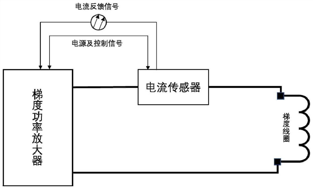
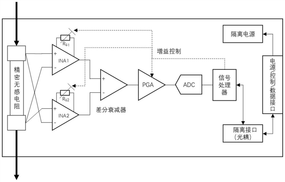
[0036] Such as figure 2 As shown, the digital current sensor used in the magnetic resonance system of this embodiment includes a precision non-inductive resistor, a first instrument amplifier (INA1), a second instrument amplifier (INA2), a differential attenuator, a programmable gain amplifier (PGA ), an analog-to-digital converter (ADC), a signal processor, an isolated power supply, and an external interface; the output power signal of the gradient power amplifier is connected to the load gradient coil after passing through a precision non-inductive resistor; The two input terminals of an instrument amplifier (INA1) are connected to the two input terminals of the second instrument amplifier (INA2) in reverse; the output terminals of the first instrument amplifier (INA1) and the second instrument amplifier (INA2) are respectively connected to the differential attenuator The positive and negative input terminals and the output terminal of the differential attenuator are sequen...

Embodiment 2

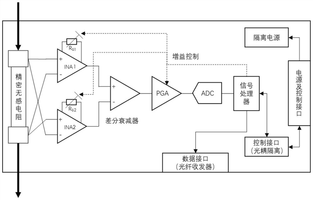
[0040] Such as image 3As shown, the structure and principle of the digital current sensor of this embodiment is roughly the same as that of Embodiment 1, the difference is that the digital current sensor of this embodiment also includes a fiber optic transceiver, and the external interface includes a power line end and a control line end. The signal processor sends the data signal to the gradient power amplifier through the optical fiber transceiver, and receives the control signal of the gradient power amplifier through the external interface. The digitized current signal can directly enter the control system processor (such as DSP or FPGA, etc.) of the gradient power amplifier to participate in the calculation, eliminating the need for additional analog signal circuits on the digital control board, and the integrated structure is simple.

[0041] The working process of the digital current sensors of the above two embodiments is as follows.

[0042] The current I of the out...


PUM


Abstract

The invention discloses a digital current sensor for a magnetic resonance system. The digital current sensor comprises a precision non-inductive resistor, two instrument amplifiers, a differential attenuator, a PGA, an ADC, a signal processor and an external interface; an output power signal of a gradient power amplifier is connected to a load gradient coil after passing through the precision non-inductive resistor; the voltages of two ends of the precision non-inductive resistor are amplified by the two instrument amplifiers in a crossed manner; the output ends of the two instrument amplifiers are connected with the positive-phase input end and the negative-phase input end of the differential attenuator respectively; the output end of the differential attenuator is sequentially in cascadeconnection with the PGA, the ADC and the signal processor; the signal processor is connected with the gradient power amplifier through an external interface. According to the digital current sensor for magnetic resonance system of the invention adopted, an electrically isolated digital data interface is provided; the design of the gradient power amplifier is simplified, and the performance of thegradient power amplifier meets the requirements of current output precision, amplitude and frequency range of gradient control of the magnetic resonance imaging system. The integrated structure is simple; and the cost is low.

Description

technical field [0001] The invention relates to the field of magnetic resonance systems, in particular to a digital current sensor for the magnetic resonance system. Background technique [0002] The current sensor is a detection device that can feel the information of the measured current, and can transform the information sensed by the detection into an electrical signal that meets certain standards or other required forms of information output to meet the requirements of the information. Transmission, processing, storage, display, recording and control requirements. According to different measurement principles, current sensors can be mainly divided into shunts, electromagnetic current transformers, electronic current transformers, etc. [0003] In the magnetic resonance gradient system, fast and high-precision detection of the current flowing through the gradient coil is required to realize precise control of the current. Due to the need to measure the DC component of ...

Claims


Application Information

Patent Timeline
IPC IPC(8): G01R19/25G01R33/36
CPCG01R19/25G01R33/36
Inventor 戴光宝陈启兴
Owner 苏州众能医疗科技有限公司
Why Eureka
Try Eureka