
High-voltage device coil assembly machining equipment

A technology for processing equipment and coils, applied in high-voltage air circuit breakers, high-voltage/high-current switches, electrical components, etc., can solve problems such as low work efficiency, achieve stable welding, strong and sufficient welding, and reduce the defective rate.

Inactive Publication Date: 2021-01-08
HUZHOU TEACHERS COLLEGE
View PDF0 Cites 0 Cited by
  • Summary
  • Abstract
  • Description
  • Claims
  • Application Information

AI Technical Summary

Problems solved by technology

[0005] The purpose of the present invention is to address the deficiencies of the prior art, by setting the laying mechanism to drive the falling coil to lie down, and then using the lifting mechanism to lift the lying coil at the output end, and to complete the adjustment of the terminal of the coil during the lifting process , so that the terminal is located at the uppermost end of the coil, and then determining the position of the coil is conducive to precise welding with the static contact. It solves the technical problem that the coil assembly in the circuit breaker needs to ensure the accuracy of its welding and assembly when processing. At present, it relies on tooling to process sequentially, and its work efficiency is extremely low.

Method used


Image

  • High-voltage device coil assembly machining equipment
  • High-voltage device coil assembly machining equipment
  • High-voltage device coil assembly machining equipment

Examples


Embodiment 1

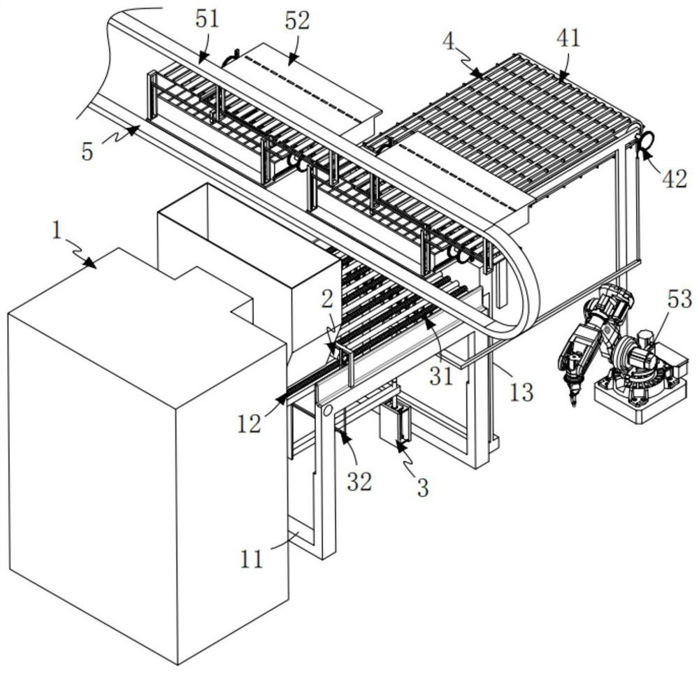
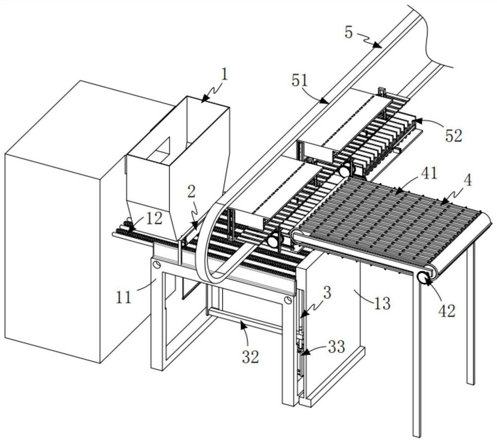
[0057] Such as figure 1 , figure 2 As shown, a high-voltage coil assembly processing equipment includes:

[0058] The laying mechanism 1 includes a frame 11, several groups of first transmission components 12 that are rotatably arranged on the frame 11 and extend along the length direction of the frame 11, and are arranged on the first The output end of the transmission assembly 12 and the seat plate 13 installed on the frame 11, the first transmission assembly 12 is driven by the first drive mechanism 14 for synchronous transmission;

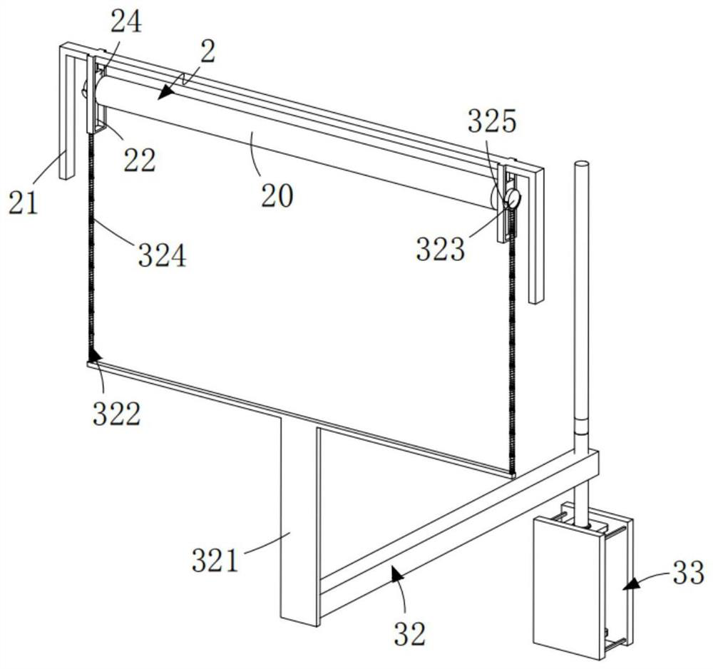
[0059] A height limiting mechanism 2, the height limiting mechanism 2 is installed on the frame 11 and arranged along the width direction of the frame 11, the roller shaft 20 of the height limiting mechanism 2 is driven to rotate by the second drive mechanism 25;

[0060] The lifting mechanism 3, the lifting mechanism 3 includes a clamping assembly 31 disposed at the output end of the first transmission assembly 12 and a second transmission ...

Embodiment 2

[0098] Such as Figure 11 to Figure 12 As shown, the components that are the same as or corresponding to those in the first embodiment are marked with the corresponding reference numerals in the first embodiment. For the sake of simplicity, only the differences from the first embodiment will be described below. The difference between this embodiment two and embodiment one is:

[0099] further, such as Figure 12 As shown, the positioning assembly 52 includes a horizontal pushing assembly 521 and a vertical pressing assembly 524;

[0100] The horizontal push assembly 521 includes a flat push cylinder 522 arranged on the bottom frame 514 with the telescopic end facing the limit seat 515 and a push plate 523 arranged on the telescopic end of the flat push cylinder 522;

[0101] The vertical pressing assembly 524 includes a transmission rack a525 fixedly connected to the telescopic end of the horizontal push cylinder 522, a transmission gear a526 meshed with the transmission rac...


PUM


Abstract

The invention relates to high-voltage device coil assembly machining equipment comprising a laying mechanism, a height limiting mechanism, a lifting mechanism, a static contact mechanism and a weldingmechanism. The laying mechanism comprises a rack, a first transmission assembly and an in-place plate, and the first transmission assembly is driven by a first driving mechanism to perform synchronous transmission; the height limiting mechanism is mounted on the rack and arranged in the width direction of the rack; the lifting mechanism comprises a clamping assembly and a second transmission assembly, and lifting of the clamping assembly is driven and transmitted by a third driving mechanism; the static contact transmission mechanism comprises a static contact positioning tool and a third transmission assembly; and the welding mechanism comprises an adjusting assembly, a positioning assembly and a welding hand, the positioning assembly and the welding hand are arranged above the adjustingassembly, and the positioning assembly and the lifting mechanism are synchronous and are in reverse transmission. The technical problem that when a coil assembly in a circuit breaker is machined, thewelding and assembling accuracy of the coil assembly needs to be guaranteed, and the working efficiency of the coil assembly is extremely low due to the fact that the coil assembly is sequentially machined through tools at present is solved.

Description

technical field [0001] The invention relates to the technical field of coil assembly, in particular to a high voltage device coil assembly processing equipment. Background technique [0002] With the rise of DC transmission grids, high-voltage DC circuit breakers are particularly important for carrying and breaking DC power. At the same time, the reliability requirements for life are also quite high, usually 30 years. The conductive main circuit structure plays the role of carrying the flow in the high-voltage DC circuit breaker, and the core component is the vacuum interrupter. However, the breaking time of the HVDC circuit breaker is at the millisecond level, and the too fast opening and closing speed affects the life of the vacuum interrupter, and the harsh environment further reduces the life of the vacuum interrupter. [0003] The patent document with the patent number CN2018100156499 discloses a conductive main circuit structure for high-voltage DC circuit breakers, i...

Claims


Application Information

Patent Timeline
IPC IPC(8): H01H11/00H01H33/66
CPCH01H11/00H01H33/66H01H33/6606
Inventor 张晓英姚亨铭陈韫慧徐燕
Owner HUZHOU TEACHERS COLLEGE
Learn More