Calcium aluminate thermionic emission device and preparation method

An emission device and electron emission technology, which is applied in the manufacture of thermionic cathodes, solid thermionic cathodes of discharge tubes, circuits, etc., can solve the problems of low thermoelectric conversion efficiency of thermionic emission devices, etc. work, reducing the effect of loss

Pending Publication Date: 2021-01-08
SOUTHEAST UNIV
View PDF5 Cites 0 Cited by
  • Summary
  • Abstract
  • Description
  • Claims
  • Application Information

AI Technical Summary

Problems solved by technology

[0005] The main purpose of the present invention is to provide a new type of thermal electron emission device using calcium aluminate derivatives as thermal emitter materials, so as to solve the problem that the thermoelectric conversion efficiency of the thermal electron emission device is too low

Method used


Image

  • Calcium aluminate thermionic emission device and preparation method

Examples


Embodiment 1

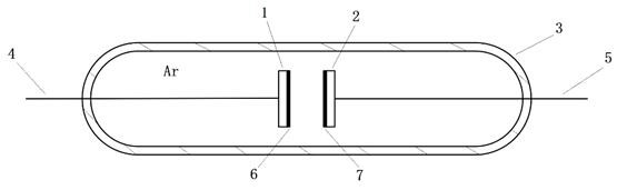
[0032] Such as figure 1 As shown, a thermionic emission device using calcium aluminate derivatives as thermal emitter materials includes:

[0033] A hot cathode electron emitter 1, a hot electron receiver 2, and a sealed quartz tube 3 for placing and fixing the hot cathode electron emitter 1 and the hot electron receiver 2. Both the hot cathode electron emitter 1 and the hot electron receiving stage 2 are based on molybdenum sheet, the hot cathode electron emitter 1 has a new material C12A7: C- / C coating 6, and the hot electron receiving electrode 2 has a rare earth oxide coating 7. The hot cathode electron emitter 1 is connected to the hot electron receiving stage 2 to lead out the hot cathode lead wire 4 and the receiving stage lead wire 5 respectively, and both the hot cathode lead wire 4 and the receiving stage lead wire 5 are made of molybdenum wire. The hot cathode electron emitter 1 and the hot electron receiver 2 are vertically fixed in the middle of the quartz tube ...

Embodiment 2

[0035] Such as figure 1 As shown, a thermionic emission device using calcium aluminate derivatives as thermal emitter materials includes:

[0036] A hot cathode electron emitter 1, a hot electron receiver 2, and a sealed quartz tube 3 for placing and fixing the hot cathode electron emitter 1 and the hot electron receiver 2. Both the hot cathode electron emitter 1 and the hot electron receiving stage 2 are based on molybdenum sheet, the hot cathode electron emitter 1 has a new material C12A7: C- / C coating 6, and the hot electron receiving electrode 2 has a rare earth oxide coating 7. The hot cathode electron emitter 1 is connected to the hot electron receiving stage 2 to lead out the hot cathode lead wire 4 and the receiving stage lead wire 5 respectively, and both the hot cathode lead wire 4 and the receiving stage lead wire 5 are made of molybdenum wire. The hot cathode electron emitter 1 and the hot electron receiver 2 are vertically fixed in the middle of the quartz tube ...

Embodiment 3

[0038] Such as figure 1 As shown, a thermionic emission device using calcium aluminate derivatives as thermal emitter materials includes:

[0039] A hot cathode electron emitter 1, a hot electron receiver 2, and a sealed quartz tube 3 for placing and fixing the hot cathode electron emitter 1 and the hot electron receiver 2. Both the hot cathode electron emitter 1 and the hot electron receiving stage 2 are based on molybdenum sheet, the hot cathode electron emitter 1 has a new material C12A7: C- / C coating 6, and the hot electron receiving electrode 2 has a rare earth oxide coating 7. The hot cathode electron emitter 1 is connected to the hot electron receiving stage 2 to lead out the hot cathode lead wire 4 and the receiving stage lead wire 5 respectively, and both the hot cathode lead wire 4 and the receiving stage lead wire 5 are made of molybdenum wire. The hot cathode electron emitter 1 and the hot electron receiver 2 are vertically fixed in the middle of the quartz tube ...


PUM

PropertyMeasurementUnit
diameteraaaaaaaaaa
thicknessaaaaaaaaaa
diameteraaaaaaaaaa

Abstract

The invention discloses a calcium aluminate thermionic emission device and a preparation method. According to the invention, a carbon derivative C12A7:C- / C with low work function and good conductivityis used as a novel coating material of a hot cathode electron emission electrode while a rare earth oxide coating is used to improve the electron absorption capability of a receiving electrode, and aspace between the emission electrode and the receiving electrode is filled with a low-vacuum argon atmosphere, so that the transmission process of heat emitting electrons from the emission electrodeto the receiving electrode is changed into plasma transmission from vacuum transmission so as to reduce the loss in the hot electron transmission process; and in a current thermionic emission device,a thermionic cathode emits electrons in an electric heating mode to obtain electron beams, and the thermionic emission device allows heat emission in a light heating mode to achieve direct conversionof thermoelectric energy and improve conversion efficiency.

Description

technical field [0001] The invention relates to a novel thermal electron emission device technology, which belongs to the technical field of thermoelectric energy conversion. Background technique [0002] Thermionic emission device is a device that directly converts thermal energy into electrical energy by using thermionic emission phenomenon, and is currently the energy converter with the highest static thermoelectric conversion efficiency. In a thermionic emission device, metals or alloys such as tungsten and molybdenum are generally used as emitters and receivers to generate thermal electrons by means of thermal emission. In a thermionic emission device, the electrode materials of the emitter and the receiver have a great influence on the thermoelectric conversion efficiency. For thermionic emission materials to have good emission performance, the materials need to have a low work function. The smaller the work function, the better the effect of thermionic emission. [...

Claims


Application Information

Patent Timeline
Patent Type & Authority Applications(China)
IPC IPC(8): H01J1/14H01J1/144H01J1/146H01J9/04
CPCH01J1/144H01J1/146H01J1/14H01J9/04
Inventor 季聪顾璠
Owner SOUTHEAST UNIV
Why Eureka
Try Eureka