
Portable catenary suspension state detecting and monitoring system

A suspension state and monitoring system technology, applied in CCTV systems, components of TV systems, TVs, etc., can solve the problems of low inspection efficiency, large investment of manpower, material and financial resources, inaccurate or perfect basic data, etc. , to achieve the effect of reducing the demand for skylights and manual input, reducing operation risks, and improving safe operation guarantees

Inactive Publication Date: 2021-01-08
领视科技成都有限公司
View PDF0 Cites 1 Cited by
  • Summary
  • Abstract
  • Description
  • Claims
  • Application Information

AI Technical Summary

Problems solved by technology

However, the existing vehicle-mounted detection equipment mainly realizes the detection of the main line. To realize the full coverage of the hub area, station side line, tie line, bureau interface, branch line and other lines requires a lot of manpower, material resources and financial resources;
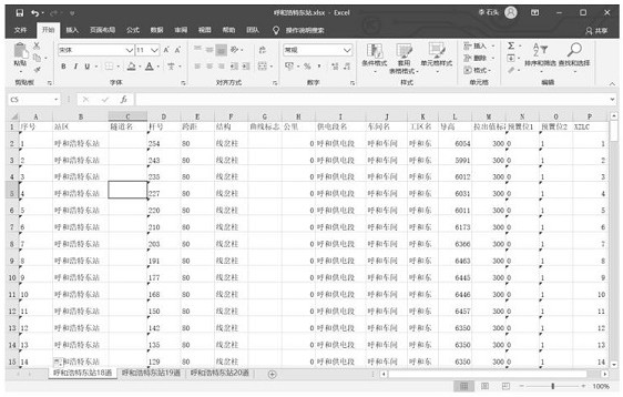
[0005] 2. Existing vehicle-mounted detection equipment and ordinary portable detection equipment must completely rely on the accurate basic data of the line to be inspected, while the basic data of the hub area, station side line, tie line, bureau interface, branch line and other lines are often not accurate. Accurate or perfect, inspection efficiency is greatly reduced

Method used


Image

  • Portable catenary suspension state detecting and monitoring system
  • Portable catenary suspension state detecting and monitoring system
  • Portable catenary suspension state detecting and monitoring system

Examples


Embodiment Construction

[0029] In order to make the purpose, technical solutions and advantages of the embodiments of the present invention clearer, the technical solutions in the embodiments of the present invention will be clearly and completely described below in conjunction with the drawings in the embodiments of the present invention. Obviously, the described embodiments It is a part of embodiments of the present invention, but not all embodiments. The components of the embodiments of the invention generally described and illustrated in the figures herein may be arranged and designed in a variety of different configurations.

[0030] Accordingly, the following detailed description of the embodiments of the invention provided in the accompanying drawings is not intended to limit the scope of the claimed invention, but merely represents selected embodiments of the invention. Based on the embodiments of the present invention, all other embodiments obtained by persons of ordinary skill in the art wi...


PUM


Abstract

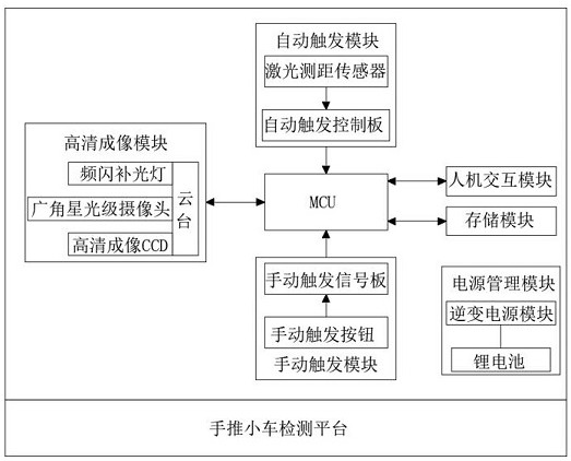
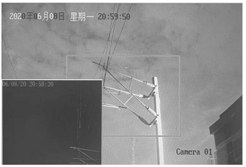
The invention discloses a portable catenary suspension state detection and monitoring system, relates to the technical field of catenary inspection, and can realize a picture-in-picture function, anda red square frame is set in a visual field image, so that under the condition that line basic data is inaccurate, a worker can quickly judge whether the contact suspension is in the visual field of the high-definition imaging CCD or not; with the adoption of the system, panoramic high-definition imaging detection of the suspension state of the contact net in any section can be realized without moving a rail car and without completely depending on line basic data, so that the high cost of the moving rail car is saved, the safety risk is reduced, and most importantly, comprehensive inspection of complex lines in station branch lines and hub areas is realized. The operation state of equipment in the section can be mastered in time, the inspection skylight requirement and labor investment arereduced, the operation risk is reduced, the safe operation guarantee of the equipment is improved, meanwhile, the system is easy to use, and the use and maintenance cost of the detection system is greatly reduced.

Description

technical field [0001] The invention relates to the technical field of catenary inspection, in particular to a portable catenary suspension state detection and monitoring system. Background technique [0002] The catenary and its support and suspension device are important power supply equipment for electrified railways, and there is no backup equipment for outdoors. In order to ensure the safety and reliability of the catenary power supply, the power supply department must periodically inspect and maintain the catenary and its supporting suspension devices. [0003] The traditional catenary suspension state detection and monitoring device mainly faces the following problems during the inspection process: [0004] 1. Lines such as hub areas, station side lines, tie lines, office junctions, and branch lines are often weak points for inspection and maintenance, and they are also high-risk points for failures. However, the existing vehicle-mounted detection equipment mainly ...

Claims


Application Information

Patent Timeline
IPC IPC(8): H04N7/18H04N5/45H04N5/247H04N5/235H04N5/372
CPCH04N7/18H04N5/45H04N23/74H04N23/90H04N25/71
Inventor 李佶林王琳珊
Owner 领视科技成都有限公司
Learn More