Polarizing plate and display device

A polarizing plate, anti-glare technology, applied in the direction of optics, optical elements, polarizing elements, etc., can solve the problems of inability to properly express anti-glare characteristics, irregularities, image distortion, etc.

Active Publication Date: 2021-01-08
LG CHEM LTD
View PDF19 Cites 0 Cited by
  • Summary
  • Abstract
  • Description
  • Claims
  • Application Information

AI Technical Summary

Problems solved by technology

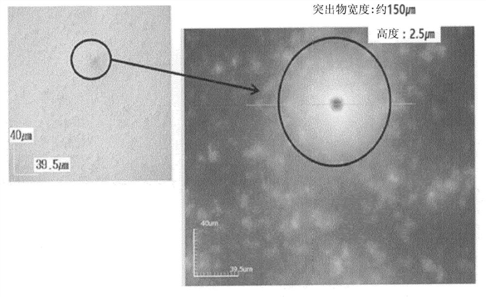
At this time, when organic particles surrounded by such inorganic nanoparticles are excessively aggregated in a direction perpendicular to the surface of the anti-glare layer, there is a problem that irregularity defects occur in which surface irregularities are too large or irregularities are often formed sex
[0008] In addition, due to these irregularities, the optical characteristics of the anti-glare layer are greatly reduced, and thus the anti-glare characteristics for controlling light scattering / light reflection, etc. cannot be properly expressed
And there may be such a defect that image distortion may occur in this area, or the reflection of light is magnified larger than the peripheral area to cause flicker, also known as the flicker (flicker) phenomenon

Method used


Image

  • Polarizing plate and display device
  • Polarizing plate and display device
  • Polarizing plate and display device

Examples


preparation example 1 to 3 and comparative preparation example 1 to 3

[0104] [Preparation Examples 1 to 3 and Comparative Preparation Examples 1 to 3: Preparation of Optical Laminates]

[0105] (1) Preparation of coating composition for forming anti-glare layer

[0106] The components shown in Table 1 below were mixed to prepare a coating composition for forming an antiglare layer.

[0107] (2) Preparation of optical laminate

[0108] Each of the above-prepared coating solutions for forming an anti-glare layer was coated on the polymer substrate described in Table 1 below by a #12mayer rod, and then dried at a temperature of 40°C for 2 minutes, followed by UV curing to form Anti-glare layer (coating thickness 4 μm). When performing UV curing, the UV lamp uses H bulbs, the curing reaction is carried out under a nitrogen atmosphere, and the amount of UV light irradiated during curing is 150mJ / cm 2 .

[0109] [Table 1]

[0110]

[0111] TMPTA: Trimethylolpropyl Triacrylate

[0112] PETA: pentaerythritol triacrylate

[0113] UA-306T: React...

Embodiment 1 to 3 and comparative example 1 to 3

[0125] [Examples 1 to 3 and Comparative Examples 1 to 3: Preparation of polarizing plate]

[0126] A polyvinyl alcohol polarizer (thickness: 25 μm, manufacturer: LG Chem) was bonded to the polymer base side of the optical laminates prepared in each Preparation Example and Comparative Preparation Example using a UV adhesive.

[0127] Then, a 40 μm thick acrylate resin film (LG Chem product, 40 μm polymethylmethacrylate base) was bonded to the other surface of the polyvinyl alcohol polarizer using a UV adhesive to prepare a polarizing plate.

experiment example 1 to 5

[0128] [Experimental Examples 1 to 5: Measurement of Physical Properties of Optical Laminates]


PUM

PropertyMeasurementUnit
diameteraaaaaaaaaa
diameteraaaaaaaaaa
diameteraaaaaaaaaa

Abstract

The present invention relates to a polarizing plate comprising: a polarizer; an optical laminate formed on one side of the polarizer and including a polymer substrate and an anti-glare layer; and a thermoplastic resin layer formed on the other side of the polarizer and including a (meth)acrylate-based resin, and a liquid panel and display device comprising the polarizing plate.

Description

technical field [0001] Cross References to Related Applications [0002] This application claims priority or benefit from Korean Patent Application No. 10-2019-0004838 filed with the Korean Intellectual Property Office on January 14, 2019, the disclosure of which is incorporated herein by reference in its entirety. [0003] The present disclosure relates to a polarizing plate and a display device. Background technique [0004] In an image display device such as an organic light emitting display (OLED) or a liquid crystal display (LCD), it is necessary to prevent a decrease in contrast and a decrease in visibility due to reflection of external light or reflection of an image. For this reason, an optical laminated film such as an anti-reflection film is formed on the surface of the image display device to reduce reflection of external light or reflection of an image by utilizing light scattering and optical interference. [0005] For example, in liquid crystal display devic...

Claims


Application Information

Patent Timeline
Patent Type & Authority Applications(China)
IPC IPC(8): G02B5/30G02B1/04G02F1/1335
CPCG02B1/04G02B1/111G02F1/133528G02B1/14G02B5/0242G02F1/133502G02B5/3033C08L2205/18C08L2666/54G02B5/3025G02F1/1335G02B1/113G02B5/305
Inventor 金珉秀沈载勋徐姃贤丘在必文柱宗金在永
Owner LG CHEM LTD
Why Eureka
Try Eureka