Eureka AIR delivers breakthrough ideas for toughest innovation challenges, trusted by R&D personnel around the world.

Full-hydraulic automatic speed change oil pressure tailstock of numerically-controlled machine tool

An automatic variable speed, CNC machine tool technology, applied in the direction of tailstock/top, turning equipment, tool holder accessories, etc., can solve the problems of reduced life, affecting the dimensional stability of parts, unfavorable actual use, etc., to improve the service life, improve Wide range of use and practical effects

Inactive Publication Date: 2021-01-12
GOODWAY MACHINE WUJIANG CORP
View PDF7 Cites 0 Cited by
  • Summary
  • Abstract
  • Description
  • Claims
  • Application Information

AI Technical Summary

Problems solved by technology

[0003] The hydraulic tailstock used in conventional CNC machine tools uses tightening blocks to fix the position of the tailstock. It is necessary to fix the tailstock to an appropriate position according to parts of different lengths. For small batches of parts, the position of the tailstock needs to be changed frequently; the holding speed of the tailstock is single , manual adjustment of the throttle valve is not conducive to actual use, it is necessary to adjust the throttle valve frequently, and because the manual adjustment is not stable, it will affect the dimensional stability of the parts, frequent adjustment of the throttle valve will reduce its life and be easily damaged

Method used


Image

  • Full-hydraulic automatic speed change oil pressure tailstock of numerically-controlled machine tool
  • Full-hydraulic automatic speed change oil pressure tailstock of numerically-controlled machine tool
  • Full-hydraulic automatic speed change oil pressure tailstock of numerically-controlled machine tool

Examples


Embodiment Construction

[0022] The implementation of the present invention will be illustrated by specific specific examples below, and those skilled in the art can easily understand other advantages and effects of the present invention from the contents disclosed in this specification.

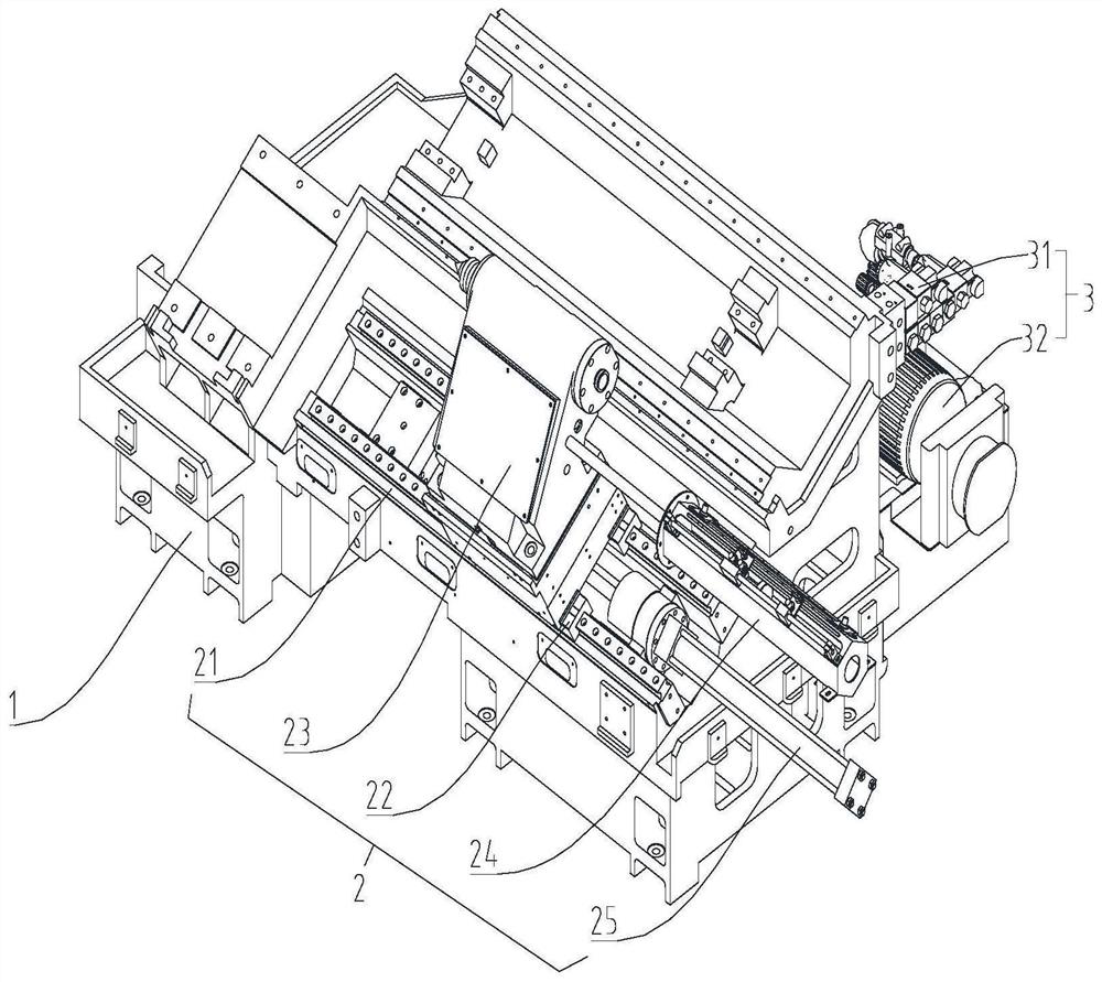
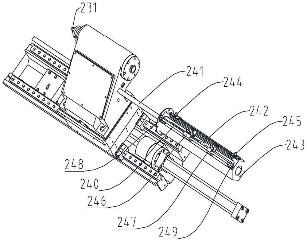
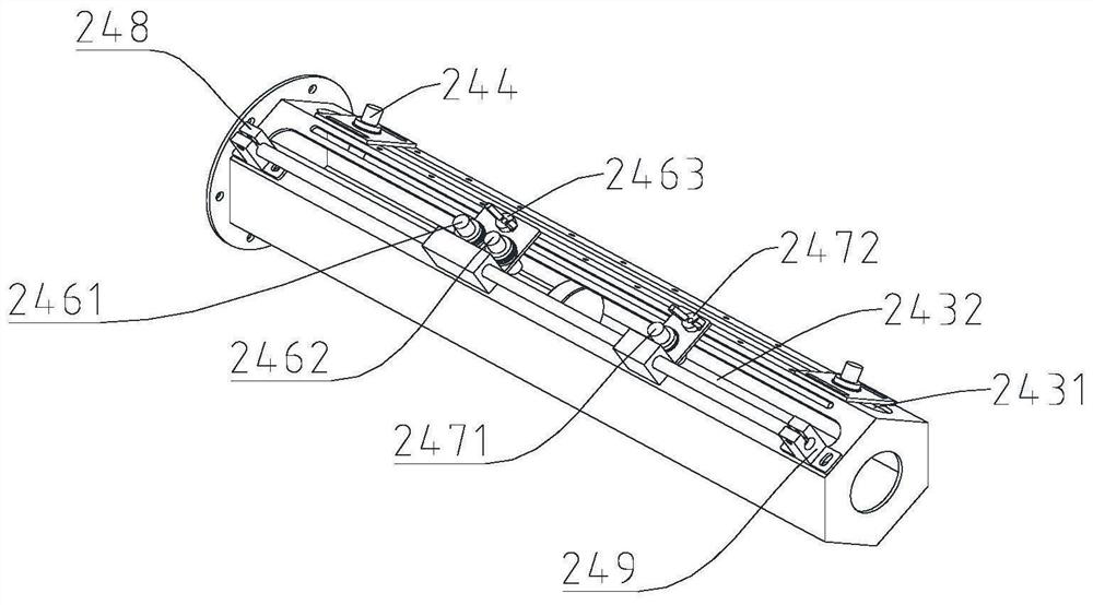
[0023] see Figure 1 to Figure 4 . It should be noted that the structures, proportions, sizes, etc. shown in the drawings attached to this specification are only used to match the content disclosed in the specification, for those who are familiar with this technology to understand and read, and are not used to limit the implementation of the present invention. Limiting conditions, so there is no technical substantive meaning, any modification of structure, change of proportional relationship or adjustment of size, without affecting the effect and purpose of the present invention, should still fall within the scope of the present invention. The disclosed technical content must be within the scope covered. At the sa...


PUM


Abstract

The invention relates to a full-hydraulic automatic speed change oil pressure tailstock of a numerically-controlled machine tool. The full-hydraulic automatic speed change oil pressure tailstock of the numerically-controlled machine tool comprises a rack, an oil pressure tailstock body and an oil pressure module, the oil pressure module and the oil pressure tailstock body are arranged on the rack,the oil pressure module is connected with the oil pressure tailstock body through an oil pipe, the oil pressure tailstock body comprises tailstock guide rails, a tailstock sliding table, a tailstockbody, a tailstock adjusting module and a tailstock oil pressure cylinder, the lower ends of the tailstock guide rails are fixed to the rack, the tailstock sliding table is arranged in the upper ends of the tailstock guide rails, the tailstock body is arranged on the tailstock sliding table, and the tailstock oil pressure cylinder and the tailstock adjusting module are arranged on the outer side ofthe tailstock body. According to the full-hydraulic automatic speed changing oil pressure tailstock of the numerically-controlled machine tool, the positions of a first detection sliding block and asecond detection sliding block can be adjusted according to parts with different lengths, the tailstock adapts to machining of various products, and the service life of an ejector pin is greatly prolonged.

Description

technical field [0001] The invention relates to an oil pressure tailstock, in particular to a fully hydraulic automatic variable speed oil pressure tailstock of a numerical control machine tool. Background technique [0002] With the increase of labor costs and the fierce market competition environment, customers have increasingly higher requirements for the automation of CNC lathes. Facing the technical and functional competitiveness of peers in the same industry, how to improve the digital control of CNC machine tools to improve processing efficiency, path, and structure simplification , easy operation and high degree of programmed automation have become the core competition in the field of CNC machine tools. Facing the gradual increase in market automation and intelligent processing requirements, the traditional manual movable tailstock gradually cannot meet the processing needs of non-standard automation and small batch parts. [0003] The hydraulic tailstock used in co...

Claims


Application Information

Patent Timeline
Patent Type & Authority Applications(China)
IPC IPC(8): B23B23/00
CPCB23B23/00
Inventor 孔元彤申宾
Owner GOODWAY MACHINE WUJIANG CORP
Why Eureka
Eureka Blog
Learn More